The AMF FXS Rebuild Project Video Series

Collapse

Desktop Ad Forum Top

Collapse

Mobile ad top forum

Collapse
X
 
  • Time
  • Show
Clear All
new posts
  • jcrubin
    Member
    • Dec 2018
    • 93

    The AMF FXS Rebuild Project Video Series

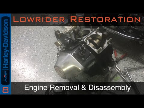
    Due to issues I was having sucking oil into a valve guide into my rear cylinder I will need to disassembly the top end of my motor. I've decided to document this work as I do with my Yamahas'. Furthermore, I have a tick in the front from an unknown clearance issue that I have the opportunity to address so I can also repair that as well.

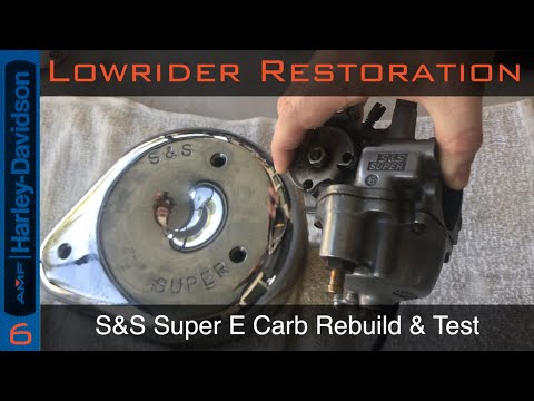
    Generally, for any work, I will begin with the prep and removal of the carbs and gas tanks. This is good stuff to know anyway. As is with all old bikes, some parts and techniques may vary. As you can see this is not the stock carb, being an S&S Short E. Keep in mind during this video that this is in preparation for several projects, also including the repair of the oil tank.

    The video starts with the carb removal, given that not everyone removing a carb is necessarily removing a tank.

    The tank removal begins with draining the tank into a gas can as shown, this is followed by the removal of the speedo/tach console.
    When removing the tank I always ensure that the upper tank bolt is always kept in place so that a tank does not accidentally fall off as shown.

    Last edited by jcrubin; 02-11-2022, 8:46 PM.
  • jcrubin
    Member
    • Dec 2018
    • 93

    #2
    In this second video in the series ,having removed the gas tanks and carbs we continue by removing the manifold that connected the carb to the heads. I notice the oxidization on the rubber rings that makes me winder if there was a vacuum leak here, its worth noting.

    This is a good time to get the throttle cable and spark plug cables out of the way, followed by the exhaust pipes. Note, my rear pipe has a different bolt. We get a first look at the oil coming through the oil coming through the valve guide with the pipe removed, as well as some other oil leaks to address on the transmission.

    This is followed by the removal of the pushrods and their tubes together using a standard technique for each one as described in the video. Note the 7/16 size tools and the ease of this operation with a kick start. Also, the spark plugs need to be removed to do this. Further note the half profile spanner being user for this, very important! Its also important to note that all parts be kept as a set as removed and the O rings generally get stick in and remain in the engine and lifters..

    With this out of the way the central oil line is loosened from both sides. If you chamfered one side like i did you can push it in and turn to remove it without loosening the heads as shown, if not you will have to wait until the hards are loose.

    Then the mounts on the other side are loosened and removed, its the large beam across the top of the engine. I reassemble all parts and nuts and washers so i don't loose them.

    Finally, the heads are loosened in a star configuration with a 9/16 spanner, taking a little tension off with each interval. Eventually they can be turned by hand and removed, except for one that stays in!!!, note the location of this special one in each head.

    Also, the read head requires a special tool for one bolt because of the reach, I use a distributor wrench to reach it for loosening. Also the shift linkage had to be removed for this along with the coil.. Funny, i noticed my seat bracket also got in the way of the rear seat removal. The rear cylinder also gets removed along with the oil line.

    As each head is removed, an inspection is done, the bore looks fine, some buildup on the piston head, no head gasket leaks, but no worries.

    With the heads out, were off to the machine shop!

    Last edited by jcrubin; 02-11-2022, 8:47 PM.

    Comment

    • jcrubin
      Member
      • Dec 2018
      • 93

      #3
      We begin this chapter by packing up and going off to the machine shop where we meet with David Rumping who did the original machining will investigate the issue with the valve and front rocker noise. During disassembly we see that there are actually no seals on these valves. We did immediately locate the cause of the front rocker box noise due to casting issues.

      Removing the boxes did have challenges due to the locktite on the nuts, heat was applied to ensure that the stud did not turn with the nut.

      A major revelation was that the valve turned out the be just fine, nothing was found to be wrong at all. Though oil was leaking through, it was caused by other engine problems.

      Dave did clean everything up for me and I took it all back home for reassembly. The cleanup also included valve stem seals. Also the front head was reworked to reduce that noise.

      Back at home we start preparation by cleaning the mating surfaces and ensuring that all of the studs are the correct hight, adjusting them if necessary. Also each nut and each thread is tested beforehand to ensure that its a good fit without bind.

      The new gaskets are laid in and the rocker boxed are applied back over the heads. Once assembled the washers and nuts are loosely fitted only to remove slack and then with a cross pattern from middle to outward the box is torqued ultimately to 175in/lbs.

      The completion of the head assembly closes this chapter...

      Last edited by jcrubin; 02-11-2022, 8:47 PM.

      Comment

      • jcrubin
        Member
        • Dec 2018
        • 93

        #4
        In part four, I find it necessary at this point to remove the oil bag so that I can bring it over to the bug ranch so that the ear can be welded. Removal of these units are not as obvious as one would think, there is a sort of dance involved. Of course, this would include amongst its tasks the removal of the oil and removable components.

        We see I managed to actually crack off another rubber mount, on the battery tray, lending to the suspicion that all of the rubber has become petrified and brittle. More new rubber mounts on the way. Following this the dance is underway to remove the tank without breaking anything else. Immediately cleaning begins, and I break up the sludge with kerosene. After agitation the drain plug is inspected and some more bad news is discovered.

        METAL... LOTS OF METAL!!!!

        Further consider, this is only from what was captured, says nothing about the oil, or what was in the filter. This cant be good. I think at the time the cylinder is good, little do I know that it is one of several failures. This was another moment when I realized this is not just a valve guide repair. With the tank completely cleaned, I ship it off to Jason for welding. Clearly there will be much more coming off of this engine, so I might as well conduct other tasks as I prepare and retool.

        I start off with a basic cleaning of the transmission area just so its not disgusting. Mind you, my assumption is that the transmission is ok and well, only needs the kicker cover tightened. I further take this time to clean each an every connector and ground point on the bike. That means shined and Deoxit on each one. This included all of the cables I broke while removing the oil tank.

        Back to the transmission, I was curious just how loose the nuts were, so I conducted a test with my in/lb wrench to see how low of a torque it would take to get them to turn. It was a disaster. So I opted to experiment with the Nordlock washers on the side covers to see if they would provide an improvement. With that, that about wraps up those tasks for part four.

        Last edited by jcrubin; 02-11-2022, 8:49 PM.

        Comment

        • jcrubin
          Member
          • Dec 2018
          • 93

          #5
          Part 5 continues with the removal of the cylinder on the front of the engine. This begins with the loosening of the base nuts with a 9/16 in a cross pattern slowly removing tension until all of the tension is gone. At that point each one can be loosened and removed with the triangular washer.

          I found that on the last of the bolts that it was turning with the stud and required propane to heat it up. Once heated there was no problem to loosen that bolt.

          I ended up using the rear jug as an example only because it was easier to see in the camera. raising it slightly only to remove the one bolt still stuck in the jug. Then, bringing the piston to about the half way position it is lifted high enough to get a rag in to catch a possible broken ring or debris. The jug is then raised off.

          Piston slap is evident, with wear on both the front and back, also, the ring openings are all pointed toward the front of the piston. This probably caused a good deal of that oil to come up through. Checking the play of the wrist-pin I can feel deflection, this is not so good.

          The cylinder is washed with soap and water to remove all dirt. also through the oil drain to confirm no blockage. It is dried and hit with air and re-oiled.

          The head gasket residue comes off with a razor blade without any issue as well as the base gasket. an inspection of the inside of the cylinder shown only minor wear due to piston slap and can most likely be cleaned up with a hone.

          The piston is removed and removal confirms significant wear in the wrist pin bushing. A quick rubber mallet test is done on the rod. I didn't hear any metal sound which is a good sign but doesn't necessarily mean that there isn't a problem.

          I will need to clean at least one of the pistons to be able to use it as a tool to check for ring wear. At the time, not knowing if I would be reusing the pistons, I assumed I would and cleaned them with kerosene and a brass brush. I noticed that there was wear along the sides of the piston face, which was not a good sign. Once the piston was cleaned I removed the rings in an ordered fashion and prepared the cylinder for ring gap testing.

          Each ring, lowered in from the bottom and put into place with the piston one at a time and measured against book values showed them to be way out of tolerance. This due to the fact that most of the rings material were drained out in my oil. It became clear that all of the rings were trash. I still wanted to know how trashy though.

          At this point everything I did was repeated on the rear cylinder. The only difference is that the same wrist pin issue is discovered. Im starting to think there might be a bottom end issue evolving. This project is going to get much bigger. I repeat the ring tests with the predictable results and then back up the cylinders to take to the machinist, because this engine will have to be removed for bottom end work having watched both wrist pins fail at the same time.

          In the end the cylinders were bored out .020 over with new pistons and rings.

          Last edited by jcrubin; 02-11-2022, 8:49 PM.

          Comment

          • jcrubin
            Member
            • Dec 2018
            • 93

            #6
            In this chapter we will be doing the standard rebuild for cleaning of an S&S Super E (shorty) carburetor. This carb has seen some considerable time in standing gas due to the bike sitting up due to the engine problems, so its a good candidate for this demonstration. Adding to this ethanol gas, is a nice recipe for a mess. The demonstration shows that even a bad carb can be brought back to new in most cases with little work.

            This carb is simple and only requires a few tools though a basic rebuild kit should be purchased before attempting. Starting with the bowl nut removed from the bottom to remove any gas, the carb is disassembled in the order as demonstrated, taking care no to loose any small parts, each inspected for wear damage or dirt collection.

            The idle needle needs to be brought to full seat so that the turns can be counted to an 1/8 of a turn and recorded so that it can be restored to the same position in the reassembly portion. Care must be taken to bull the bowl off straight and not at an angle.

            In this case we see that the float was completely stuck, though, the system has been dry and may have not been so if it were in gas. Still terrible. The float needle seat is removed from the bowl and polished first. Wear is seen on the inner race, though mild, its probably approaching the end of its service life. On the next removal, it will be replaced.

            Every other serviceable piece is cleaned and polished in the same manner. The enrichener valve also demonstrated minor wear at the needle as well but still passed inspection. Some of the brass pieces cleaned are press fitted into the main carb components and are done before going into the tank. This includes the accelerator pump nozzle in the bowl, and the emulsion tube for the enrichener.

            A mixture of simple green, distilled water and dish detergent is brought to about 70degC in the bath before putting the parts in the bring them up to temperature. The parts go through one 20min cycle before an inspection. It was determined that a second 20min cycle was ok to conduct. They were then allowed to come back down to room temp before rinsing them in a bath and blowing them out with air.

            Assembly starts along with the rebuild kit parts starting with the float bowl pieces. Quickly an inspection is made of the float bowl height between 1/8 to 3/16 from the gasket height, measured with calipers. Mine turned out to be ok so O did not need to bend the metal tab. After this, the rest of all of the pieces were bolted on, the idle jet to full seat and turned out to the original position. This will require subsequent re-adjustment on the bike.

            The main gasket is lowered across all of the parts on the car, with special attention to the o-ring on the accelerator pump nozzle. Then, carefully bringing both sides together. The final portion comes in a separate bad because the pieces are very small, the spring and the two bearings. The diaphragm for the accelerator pump only fits in one direction into the small cover.

            A special technique is employed to but that bottom cover on as described in the video using the pump rod to counteract the spring tension to push the diaphragm into position as the cover is closed. The bearing side should be lowered first though so they don't fall out.

            Should the bowl need to be opened only the long screw need be removed from the pump cover, the pump can be left closed and not reopened to remove the bowl. The rest of the seals would be added during installation onto the bike.

            Last edited by jcrubin; 02-11-2022, 8:50 PM.

            Comment

            • jcrubin
              Member
              • Dec 2018
              • 93

              #7
              In this episode of the project we will continue on with the removal of the primary, primarily in support of the removal of the engine so that it can be sent off for a bottom end rebuild. I will note that this model is a dry clutch belt driven setup so it will be a bit different than conventional models, but nothing terrible.

              This begins with the removal of the outer cover, which in my case is simply there to stop rocks from getting in or fingers from getting chewed up. Its not oil tight. My gasket is only for vibration dampening,

              A combination of Belt and oil residue is an unwelcome sign of things to come, nothing terrible, for now, but we continue onward as I assemble a quick pressure plate stay to remove the clutch as one unit. Everything with regard to clutch and friction plates seemed ok save some glazing. Once empty, a special tool is used to loosen the primary bolt. I'm not proud, I should have the correct tool on hand JIMS #2316.

              To remove the pulley requires pullers, luckily I had that and it came off without issue. for the Nut in the back, locking tabs are hammered up and keeping in mind reverse thread it is loosened and placed right back on. This requires another special tool for removal. After removal, there is a key on the spline that needs to be removed and saved. That covers all of the inner primary internal contents.

              This brings up to the starter solenoid, removed with two bolts, allow the sliding out of the Bendix. The remaining pieces for the starter can be left alone. I stop and do a quick check that the transmission mounting bolts are not loose before proceeding with any further steps, nothing crazy, just not loose.

              At this point the starter is removed, two bolts secure it, one from inside the inner primary , the other side via a long extension from the other side of the bike. Following this, the safety wire inside the inner primary is cut and removed, along with all of the bolts inside the inner primary. This also includes two external bolts of the primary going into the engine.

              With a few light taps, the primary is separated from the bike to reveal some unfortunate findings. Notably, a serious leak around the transmission area as well as an oil leak around the engine area including a belt misalignment.

              Looks like there is a lot of work ahead...

              Last edited by jcrubin; 02-11-2022, 8:51 PM.

              Comment

              • jcrubin
                Member
                • Dec 2018
                • 93

                #8
                Having separated the inner primary in the last chapter, its now time to remove the engine from the frame. For this an engine stand will really become important to do so.

                I mark the hoses first, so I reuse the same ones in the same location, having retained the correct bend over time; pulling them out of the way. This also includes ignition and other such electrical cables. There aren't much. Also, the voltage regulator is easily removed forward of the engine and cane come out at this time. The connector for the regulator comes right out of the motor case.

                With this, I want to remove any residual oil from within the case, I use a vacuum pump for this task, this is only so I don't make a mess later and for no other reason. In the next step the removal of the engine mount bolts it becomes obvious that something is wrong.....

                In removing the bolts its clear that these are not mounting bolts and have worn away causing engine deflection and vibration. Very bad. A quick test that the engine is unseated confirms its ready to be removed from the chassis.

                Il also point out that there were no shims under this engine when it was removed.

                I mount the engine into the stand, using these wrong bolts just to hold it safely in place, and start a degreasing exercise on the frame. While the degreaser is working I get the engine on the bench.

                We start with the removal of the stator cover to expose what was a known hairline crack for re-inspection. As seen, its gotten so much worse and the cable is completely destroyed, the stator is unserviceable and is removed. All of these charging system items are collected and stored in one box for later.

                Turning the engine around I remove the timing and quickly scribe in some timing marks before removing the ignition; working the ignition wiring out of the cam cover. This is followed by the rotor bolt, holding the engine. These items are stored together as ignition system.

                Now I pull the lifters and put them in a special market container by position, Then loosening the bolts from the cam cover. I assemble a setup for my cam cover puller, thankful that I drained much of the oil before with the vacuum pump.

                We start with a quick inspection looking at all of the markings making sure everything matches up. They did. Another inspection of the cam showed it in perfect condition. I jumped out of order for a second to do this, I should have removed the rollers first, so I put the cam back, and did it right.

                I removed the breather and checked for obstructions in the mesh and found none, it was cleaned and re-inserted. The next task was oil pump removal. Everything was 7/16 for this task. After this my oil pressure gauge was removed. exposing the spring and filter below. This too, unobstructed.

                I correctly reassemble everything with the lifters and rollers to disassemble correctly and place them in the ordered container. All bearings and seals on the cam cover will be replaced as well.

                Everything is ready for the machine shop.

                Last edited by jcrubin; 02-11-2022, 8:52 PM.

                Comment

                • farmall
                  Senior Member
                  • Apr 2013
                  • 9983

                  #9
                  Cool. The more video training aids out there the better.

                  Comment

                  • jcrubin
                    Member
                    • Dec 2018
                    • 93

                    #10
                    Having removed the engine and primary in previous videos it was noticed that there was quite an amount of transmission oil everywhere requiring closer inspection. A first test of the actual gear showed severe deflection. First we will give the bike a well needed bath, covering certain areas first and applying a de-greaser as well as a good agitation.

                    A quick jump over back to the engine only to point out some damage that was discovered after the removal video that I felt important to include, these items would be repaired obviously but I wanted the damage from the mis-alignment to be seen.

                    Returning to the garage, a quick discussion of the removal strategy starts with the removal of the chain itself, using a chain breaker tool. The goal here is to reuse the chain, removing with the proper tools. With the master link removed, the chain is negotiated out from the sprockets and stored, because it is disgusting.

                    This brings us to the worst most over engineered shift linkage on the planet, though not a problem to remove, i'm often amazed when I stare at this and wonder what they were thinking when they designed this. The clutch cable is move forward to release it from the connector and pushed back in.

                    Two of the transmission cover nuts are removed to release the starter mount allowing the starter to be swung out of the way. I also remember the hose guide needs to be loosened and moved out of the way.

                    At this point the 9/16 transmission mounting bolts are loosened from under the bike. A wiggle confirms this and the transmission is easily removed and put up on the bench.

                    With the transmission out of the way, focus is turned to the engine guard, which is removed and inspected, it would appear there was a bottom out event. This might have been one of the causes of the misalignment. This plate will be cleaned and repainted.

                    During this time, the bike will be washed again. Once dried some cosmetic and protectant work is done on the lower frame, these are non visible areas and only for protection.

                    At this point its time to dive into the transmission, but thats for another video!

                    Last edited by jcrubin; 02-11-2022, 8:54 PM.

                    Comment

                    • jcrubin
                      Member
                      • Dec 2018
                      • 93

                      #11
                      This video starts a several part sub series that makes up the transmission restoration project for this motorcycle. As it was already discovered that the transmission had also suffered some degree of damage, the extent, not known however, enough so that a complete disassembly will be required to accomplish the goal.

                      The unit is broken into three groups, the ratchet top, the case and the starter. This will start with the removal of the ratchet top. This will be followed by the removal of the sprocket and associated components.

                      With the shift release arm removed the kick cover is ready to come off. All of the nuts were secured with nord-locks previously so they will need to be retrieved and collected because they are expensive. This was followed by the throw-out and rod.

                      The next job was the starter clutch assembly but i wanted to see what a magnet would capture, it was absolutely terrible, tons of metal in the oil caught on the magnet.

                      Having no was to support the transmission to remove the starter nut, I re-mounted it into the motorcycle frame just to break the tension, then it went back on the bench,

                      Upon removing the starter components, I stop quickly and measure the countershaft end-play as it stands. Looking for .005-6 I'm finding about 17-18thou... Which is terrible. terrible.... I assumed it was an end shaft bushing issue in the video, but I was wrong those were fine, it just needed a larger shim, that's for later though...

                      Now the kicker assembly is completely disassembled and stored. The one way clutch for the starter proved to be a challenge, using oil didnt work, I got a good tool from napa 776-9073, but this also required propane as the mating surfaces were rusted. This process took patience. This allowed the removal of the rest of the starter components. Behind this is the Shaft bearing plate which is removed.

                      Next is the removal of both shift forks, removed following removal of the shift fork shaft. The Plate also held in the countershaft allowing it to be pushed through, allowing the whole counter shaft assembly and end shim to be removed.

                      Now the main shaft is free, a few light taps with a rubber mallet the bearing from the case. once free, the shaft retainer is removed to allow the complete shaft removal, leaving behind the components inside and the final drive gear.

                      With the case emptied, a final look at the main shaft shows deep gouging. The next video will allow the transmission healing to begin.

                      Last edited by jcrubin; 02-11-2022, 8:55 PM.

                      Comment

                      • jcrubin
                        Member
                        • Dec 2018
                        • 93

                        #12
                        Part 11 continues the tear-down after the disassembly from the transmission case. This will start with the disassembly with the kicker cover. The first observation is that the 40lb/ft nut is loose, only held by the lock washer, so a check will be done to see if there was any damage after disassembly. It was found the old cover was too far gone, and the bushing destroyed, a new cover was used for this portion, replacing the cleaned components into the new cover.

                        Further checks of the shaft and kicker gear showed severe damage, a whole kicker kit was was purchased from Sifton for this as nothing was salvageable. Alignment of the shaft and gear for assembly is not well explained in the book, I've taken extra time to explain it here. Another challenge is setting up the shaft end-play with the supplied bushing which is only a few thou/in. I've had to adjust this on a belt sander and keep re-assembling until the end-play was perfect.

                        The next set is the disassembly of the shift assembly starting with the removal of the top plug which needs to be drilled out to gain access to the c-clip. I should have removed the shifter from the side first, but that was just not going to happen without these parts removed first, ultimately, all pieces would be disassembled.

                        Once the shifter piece was removed, it was disassembled as a component, noting it has an oil seal. Cleaning now begins for all individual pieces. Next are the springs and neutral switch, that was the extent of what was removed from the cover, so the cover would be washed and de-greased. This is followed with the cleaning and oiling of the springs and their re-installation.

                        I then pulled the outer oil seal and spacer from the case for preparation to bring to the shop. I head over to the bug ranch and get started on stripping the old mainshaft of the gear and bearing. Then, over to the 20ton press to finish the job. A quick look at the shaft and bearing race shows everything in good condition.

                        Next the main bearing will be removed from the case, i've assembled a special jig to pull the bearing out. It was NOT fast, but it was effective. With the halftime inspection it took over half an hour using this method, but nothing broke.

                        Ill note that this is exactly 50% of the entire FXS lowrider project right here!!!

                        The transmission case then went into the parts washer for a much needed bath. While it was cooling down I took the time to replace the seal for the shifter using a special took I made for the job.

                        Back at the garage every single individual top component of the transmission is cleaned/inspected/oiled and re-assembled. The Neutral switch gets PTFE on the threads and the top C-clip did not come with the rebuild kit.

                        One bolt is pre-added before the shifter goes back on, very important. I shift through all gears as a test and finally hammer in a new plug on top. This finishes this episode of the transmission rebuild.

                        Last edited by jcrubin; 02-11-2022, 8:56 PM.

                        Comment

                        • jcrubin
                          Member
                          • Dec 2018
                          • 93

                          #13
                          In part 12 of this series where we will begin the reassembly of the transmission with the arrival of the custom modified mainshaft from Ray [saddlebagrail]. The custom work and seals are evident upon inspection. Everything looks really good.

                          I stopped by the bug ranch quickly with the old main bearing to press the bearing out of the race. My mother was in town to join us for the bearing extraction at the ranch. I'd ordered a replacement bearing from J&P. In this rare occasion I was quite disappointed with what had arrived, some Tucker Rocky Chinese garbage. So I'd searched for and ordered the original SKF bearing. I usually have great luck with J&P, this was a rare occasion. The main drive gear bearing and other parts from them was just fine. I do have the special tool for the bearing installation.

                          For all of the bearing work to make things easier, I threw everything in the freezer while I set up everything. I didn't expect too much resistance pressing it into the race, but this bad boy fell right in, I wasn't comfortable with that. I decided to peen the inside of the race and use some red Locktite as well to add some out bearing seating security. With that the bearing pressing in appropriately.

                          Now I start to assemble a wooden mount for the transmission case so that it can be safely placed on the press. Once situated, the main bearing is pulled from the freezer and staged, along with the special installation tool. Keeping in mind the correct direction, the tools allows for easy installation at the correct depth.

                          Now the gears are inspected and cleaned up as they are prepared to be installed onto the new mainshaft. The first of the gears are pressed onto the shaft. This is followed by the bearing and race onto that gear assembly. Then, finished off with a new lock washer and nut, into a softjaw vice and torques to 55ft/lbs. Finally, securing the locking tabs to completion.

                          The other gears and components are cleaned and inspected, though before the day ends, the case is turned over and some green locktite added to the base of the studs for sealing.

                          The next day continues with the greasing of all areas of the final drive gear as its inserted into the main bearing. As the shaft is then inserted through, all of the parts are lined up in order for correct assembly onto the shaft, making its way through to the final drive gear seal. It can only go so far before the snap ring need to be brought into position so the shaft can be brought into further.

                          To get the last of the shaft in, the bearing race needs to be pressed in. So the gears don't fall on the shaft they are taped into position, the bearing and race is then pressed in to full seat. After which the tape is removed.

                          I temporarily apply the bearing race retainer plate so nothing slips for now. after which the spacer and seal receive ample grease. The seal and spacer are brought together over the shaft. The wooden stand needs to be modified again to accommodate the shaft as the transmission goes back onto the press to seat the seal and spacer.

                          With that the mainshaft portion of the installation is completed, ending this portion of the installation.

                          Last edited by jcrubin; 02-11-2022, 8:57 PM.

                          Comment

                          • jcrubin
                            Member
                            • Dec 2018
                            • 93

                            #14
                            This episode continues with the reassembly of the 4 speed transmission. This will deal with the counter-shaft assembly. This includes disassembly, cleaning, inspection, and reassembly. The ends of this years counter-shaft has pressed in caged bearings, I will have to remove these and replace them as well.

                            Pulling these bearings was a bit of a challenge as one of them was frozen requiring a bit of a break on the press to get it moving, it sounded like a bullet when it broke free. A mild rust line was seen as the cause, followed by much contamination from the last build. The rest could be cleaned and saved.

                            Standard cleaning procedures are done to prepare followed by oil as the gears are inspected. The bearings are tossed in the freezer as staging is done to setup for the pressing task. Each side gets a bearing pressed in just under the lip chamfer. With that task completed, all of the other pieces are washed for inspection.

                            I used new bushings, though one of the bushings provided did not fit properly, its a very specific fit, calling J&P they sent me rush delivery a new bushing for free without question. This was a minor delay, but when the new one arrived it fit and the first of the assembly was started. Everything oiled as installed.

                            With the counter-shaft completed, the end-play measurement and adjustment will need to be done. Dropping the counter-shaft in with the shaft and old shim, holding the transmission sideways its pushed in and then the feeler gauge is used to measure the endplay. As 14 is too wide, the current shim is measured so the extra .010 thickness could be measured and a new shim ordered.

                            The new shim is then inserted providing for about .005 inches of end-play With the final assembly of the counter-shaft, this time the new shaft from the kit is used with the provided seal. The notch of the shaft must be turned to fit the locking plate on the other end properly at 8 o'clock.


                            Last edited by jcrubin; 02-11-2022, 8:58 PM.

                            Comment

                            • jcrubin
                              Member
                              • Dec 2018
                              • 93

                              #15
                              In this episode we continue with the 5th part in the transmission series, continuing from the counter-shaft assembly and installation. Now we move onto the shift forks. This begins with the installation of the retaining plate and deflector, the screws will be installed with blue locktite, tightened to 105 in/lbs.

                              The next step will be the preparation of the kick starter pieces which will be cleaned and inspected. Pieces from the kit will replace some from the non reusable items. Each item is re-added onto the shaft. I'd noticed that the end nut would not go on, and found i had a slight burr on the thread, requiring a quick minor repair. I did decide however, to opt for a new end nut for this job since the shaft was new. In order to torque the nut properly I mounted the transmission into the bike to hold it in place, torquing to 40ft/lbs. Followed directly by bending the locking tabs for that nut.

                              Now, moving onto the shift forks, washing and inspection begins, without disassembly, so that they can be measured in the transmission. They are reinstalled in the unit using a new shift fork shaft from the rebuild kit. The sprocket also needs to be snugged down on the shaft as well. The nut is reverse thread.

                              Once the the sprocket is tightened down, the top cover is shifted into neutral so that my special tool JIMS 963385-78A, Fork centering tool, can be installed onto it, establishing the neutral points for the cover that can be transposed into the transmission at the shift forks. The shift forks are held into correct center by the tool. The centering can be measured on each.

                              As measurement begins, problems are quickly seen with centering. .75/.84 for the counter-shaft fork. .75/.158 for the main-shaft. With these measurements, it is understood what shims need to be added and removed and how much. so the forks can now be disassembled one at a time, to see what shims are inside them and what needs to be ordered to bring them back to center.

                              Last edited by jcrubin; 02-11-2022, 8:59 PM.

                              Comment

                              300 mobile ad bottom forum

                              Collapse
                              Working...
                              ;