wiring new starter ignition

Collapse

Desktop Ad Forum Top

Collapse

Mobile ad top forum

Collapse
X
 
  • Time
  • Show
Clear All
new posts
  • firstripholdmybeer
    Senior Member
    • Apr 2018
    • 338

    wiring new starter ignition

    Hey everyone just got this starter ignition from Lowbrow

    Ride through the most adverse conditions without worry about a failing ignition switch. This sealed, weatherproof and vibration-resistant ignition switch allows


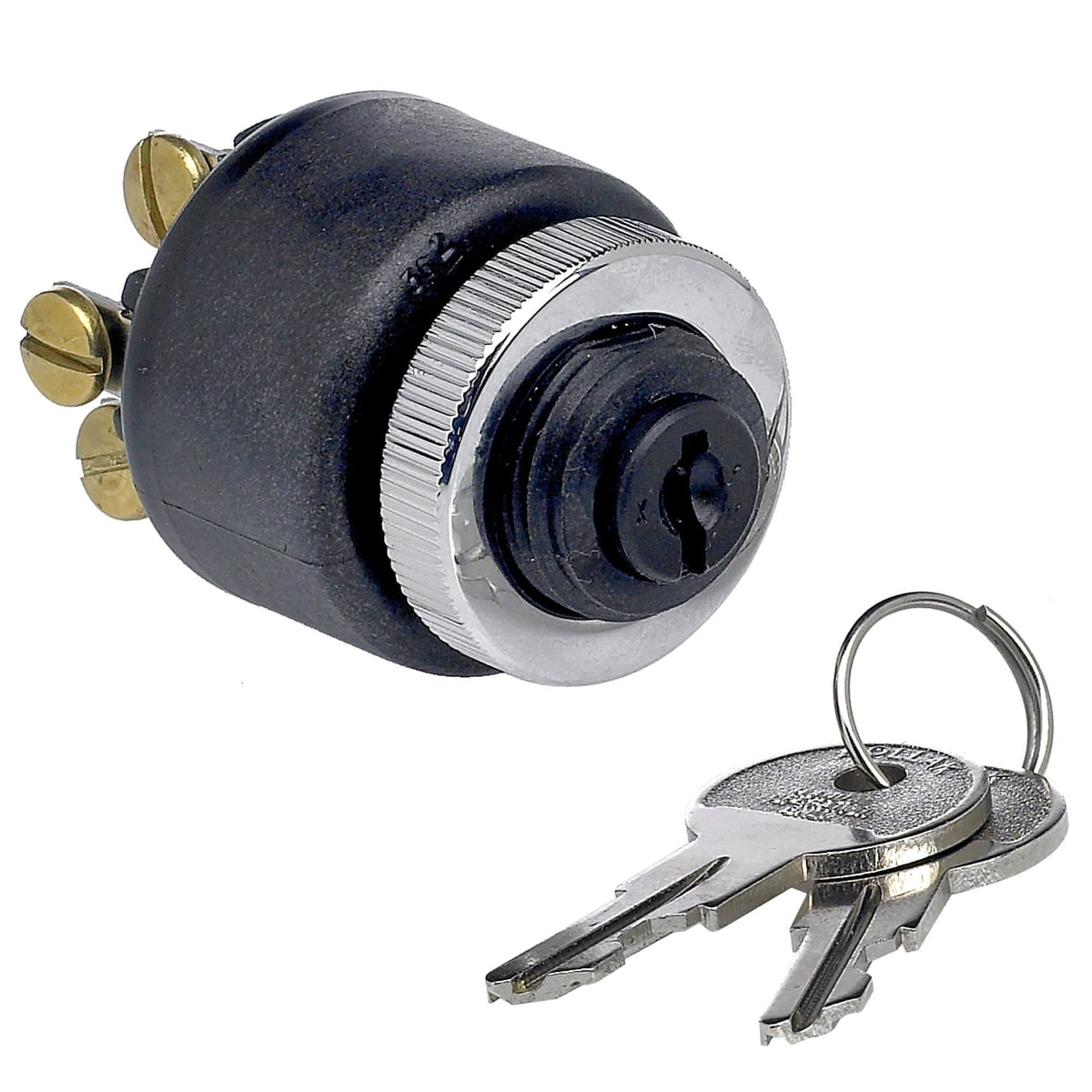
    Wondering if anyone can help me figure out any additional wires that need to be connected to the unit to get it to start? Below are pictures of Lowbrow's diagram and my wiring harness. right now I've got the RED, R/BK, and R/GY wires connected according to the diagram. I'm ASSUMING I'll need these connected as well:

    White/Black (ignition Coil)
    Red/Yellow (Start button from hand control and runs to tail light)
    Gray (Onto circuit protector then ignition) wires connected as well?

    Wondering if any of these do connect, would anyone know where? I already sent an email to Lowbrow with this question and just waiting to hear back.

    cheers!

    Click image for larger version

Name:	IMG_8250.jpg
Views:	1
Size:	297.5 KB
ID:	1343401

    Click image for larger version

Name:	IMG_6240.jpg
Views:	1
Size:	289.9 KB
ID:	1343402

    Click image for larger version

Name:	IMG_6281.jpg
Views:	1
Size:	295.0 KB
ID:	1343403
  • firstripholdmybeer
    Senior Member
    • Apr 2018
    • 338

    #2
    I tried grounding the M2 and sparks started flying. wondering how this is possible if the key wasn't in the ignition?

    Comment

    • farmall
      Senior Member
      • Apr 2013
      • 9983

      #3
      You can trace where the contacts pass current by using a multimeter with the switch installed but completely disconnected. ALWAYS do that with a new switch so you KNOW what it does in every position AND if it shorts to ground via the case. (I trust no one, and the switch assembler could be a peephead for all I know. Some switch assembler music: https://www.youtube.com/watch?v=VGeM57i9Eks )

      With every wire removed, does M2 have continuity to ground through the switch body? Place one multimeter lead on a good ground (engine, whatever) and the other on M2. Note results in every switch position. WRITE THEM DOWN.

      Then check continuity between EVERY switch position and EVERY contact and ground. Note results. You see where this is going. What's "on", 'off" and "grounded" matter so you'll know and not assume.

      I tried grounding the M2 and sparks started flying. wondering how this is possible if the key wasn't in the ignition?
      Why are you doing that? KNOW what each position DOES then WHERE the power should go.
      Last edited by farmall; 07-19-2018, 5:16 PM.

      Comment

      • tzienlee
        • Apr 2024

        #4
        Are you using a Magneto ??…. if you are not i'd say you are using the wrong switch,...
        you just need 3 positions with 3 wires,..
        1) Power in.
        2) power out Auxiliary 1,..feed to ignition, horn, turn signals, brake light,
        3) power out Auxiliary 2,...feed to lights and all auxiliary 1 components

        switch positions should be,
        1) OFF.
        2) Aux 1.
        3) Aux 2.

        if you are using a magneto you must NOT, EVER, DON'T EVEN THINK ABOUT IT, PUT POWER ANYWHERE NEAR THE MAGNETO IN ANY SHAPE OR FORM OR YOU WILL FUCK UP THE MAGNETO !!!!……. if you are not using a magneto, it's the wrong switch..
        Last edited by Guest; 07-19-2018, 4:57 PM.

        Comment

        • farmall
          Senior Member
          • Apr 2013
          • 9983

          #5
          Are you using a Magneto ??…. if you are not i'd say you are using the wrong switch,...
          Looks like it. A twenty dollar Drag Specialties switch would have solved the problem. (I don't care for special switches, modules or anything but the most basic therefore reliable and easy to troubleshoot system components.)

          The mag pic confused me briefly but I remembered he's not running one.


          1) Power in.
          2) power out Auxiliary 1,..feed to ignition, horn, turn signals, brake light,
          3) power out Auxiliary 2,...feed to lights and all auxiliary 1 components
          Do this. Not anything different except don't forget power to a starter switch (if you run one) in both positions.
          Last edited by farmall; 07-19-2018, 5:56 PM.

          Comment

          • Revelator
            Senior Member
            • Aug 2009
            • 2990

            #6
            just hook up the A B & S connections on the switch

            B is the 12 volt + from the fuse or breaker

            A supplies the Ignition, Lights, etc.

            S goes to your starter Relay.

            pretty basic. You should only be fucking with the wires on the right
            side of your wiring diagram, no need to dick with other connectors/
            connections on the other side of that 1st quick connect, (white/black,
            grey, red/yellow, etc.). that shit should already be hooked up unless
            someone modified the harness or changed shit around.

            Comment

            • firstripholdmybeer
              Senior Member
              • Apr 2018
              • 338

              #7
              Originally posted by Revelator
              that shit should already be hooked up unless
              someone modified the harness or changed shit around.
              Thanks for the response, exactly what I was looking for. I’ll test it out tomorrow. As for the left side, (gray, black/red, red/yellow, and white/black) those are all disconnected. I’ve removed the stock switches and only running a headlight toggle and this starter ignition.

              So I think the white/black (ignition coil) would be going to “A”. I could cap the Gray (kill switch). The Black/Red (start button) goes straight to start relay so that could be “S”?

              Thanks everyone for your responses gonna spend a good chunk of the weekend troubleshooting and setting up the controls if I can finish the electrical. Hope everyone has a good weekend!

              Comment

              • firstripholdmybeer
                Senior Member
                • Apr 2018
                • 338

                #8
                Originally posted by farmall
                The mag pic confused me briefly but I remembered he's not running one.
                Farmall, you seem to be a wealth of knowledge. cheers!

                So on the "M1" position I was running the stator/regulator thinking that would replace a magneto? if that's not the case would I share the Stator on the A,B, or S connections like Revelator mentions I should do, above?

                Comment

                • firstripholdmybeer
                  Senior Member
                  • Apr 2018
                  • 338

                  #9
                  Originally posted by tzienlee
                  Are you using a Magneto ??…. if you are not i'd say you are using the wrong switch,...
                  you just need 3 positions with 3 wires,..
                  Hell yes, thanks for sharing this. gonna give it a try today. On the "M1" position I was running the stator/regulator (RED) thinking that would replace a magneto? If not, would I share the stator and battery wires on the same connection?

                  thanks a bunch man!

                  Comment

                  • farmall
                    Senior Member
                    • Apr 2013
                    • 9983

                    #10
                    On the "M1" position I was running the stator/regulator (RED) thinking that would replace a magneto?

                    Is there a reason you just connect stuff without KNOWING about how wiring and what it connects work?
                    We can't hold a gun to your head to make you do the homework.

                    An alternator stator is not a magneto. If you don't know why FOR FUCKS SAKE INVEST A LITTLE TIME IN LEARNING. There is no substitute. NO SUBSTITUTE. Not a damn option. Do it the right way. Not how you think you want to do it because you don't KNOW how to do it. No shame in that game if you LEARN THE RIGHT WAY. Being spoonfed step by step is less than ideal.

                    Regulator (not "stator" but the stator feeds the regulator) wire TO the battery and "battery" positive lead can share a connection. A circuit breaker between them and the switch will protect downstream components and wires. If you STUDIED a variety of simplified wiring diagrams you would have seen examples and know the reason for wiring that way.

                    Stator feeds regulator feeds battery.

                    We really like helping others but ya need to get serious. If you'd left that stator shorted to ground then run the bike it could expensively fry the stator and you'd be buying parts after more troubleshooting.

                    Know and be able to VISUALIZE each circuit. By the time you are reasonably proficient you should be able to sketch charging and ignition and starting circuits from memory. The basics are simple. Learn them.
                    Last edited by farmall; 07-20-2018, 2:04 PM.

                    Comment

                    • MOTher
                      Senior Member
                      • Sep 2012
                      • 347

                      #11
                      What you have is a re-purposed boat switch. It works well on motorcycles because it's waterproof, and that particular one is a good quality switch, which is why Lowbrow sells them. The reason M2 sparked when you grounded it is because you had power to M1. Because the boat motor this switch is designed to control has a magneto, the kill wire from the magneto goes to M1 and M2 gets grounded, (on the boat.) Those two terminals are connected inside the switch when it's in the "off" position. That's how you turn a magneto ignited engine off, ground the kill wire.

                      The way Revelator says to wire the switch is the correct way. The long wire from the voltage regulator (not the stator, that only connects to the voltage regulator,) has to be connected to the + side if the battery somewhere. You can hook it to the battery directly, or the B terminal on the switch. It doesn't matter. That's the wire where power from the alternator, rectified and regulated, get's back to the battery to keep it charged.

                      Try something here that's not in Lowbrow's instructions. Put the key in the switch, turn it on, then push in on the key. If it moves, and I think it will, that motion will connect power to the C" terminal as long as the key is pushed in. The original function of this is to set the electric choke on the boat. If this is the case, I'm using the same switch on my Shovelhead. (I didn't get it from Lowbrow, but from the original source.) Because mine is mounted on the top motor mount, where I can reach it easily, I'm using the C function as my horn button. That'd be a pretty inconvenient place for a horn button it if you're putting this switch in the stock position on your Sportster.

                      Comment

                      • Luky
                        Senior Member
                        • May 2018
                        • 901

                        #12
                        You will need a starter relay wired to the starter as shown on the wiring diagram.
                        Those wires were not highlighted in yellow on your diagram.
                        Last edited by Luky; 07-22-2018, 9:27 AM.

                        Comment

                        • MOTher
                          Senior Member
                          • Sep 2012
                          • 347

                          #13
                          Originally posted by Luky
                          You will need a starter relay wired to the starter as shown on the wiring diagram.
                          Those wires were not highlighted in yellow on your diagram.
                          I've heard this both ways. Some say you need the relay, others say the switch itself is stoutly wired enough to use it without a relay, especially if the wire from the "S" terminal to the solenoid is of sufficient gauge and not too long. The relay on a stock Harley is so they can run a light gauge wire to the button on the handlebars, and use a fairly light duty (current wise) button/switch there.
                          Last edited by MOTher; 07-22-2018, 1:38 PM.

                          Comment

                          • farmall
                            Senior Member
                            • Apr 2013
                            • 9983

                            #14
                            The small Bosch style relay contacts aren't any bigger than those on most key switches and pushbuttons. I wouldn't worry about using a key switch to start without the relay. If a conventional handlebar switch is used I'd run the relay to drastically shorten the distance current to the solenoid windings must travel over thin wire.

                            You can get heavy duty relays and sockets with thicker gauge wires. Check a non-shit auto store. I don't have my reference handy. The Bosch style are very common.

                            Don't forget a cheap starter solenoid end cover pushbutton no matter what else you use on the electrical control side. If access sucks because of your exhaust (I refuse to run pipes which block the end cover) you can still reach the button with a screwdriver, pencil or other expedient tool. This bypasses all external switches and requires less starting current because no current is sent to the solenoid windings.

                            These work well for me. Pic shows the style. It's widely available. https://www.ebay.com/itm/Pyramid-Pus...-/222536275694

                            I've also used the stamped style and the overpriced but nice Spyke unit. (I paid 15 bucks for the working starter the Spyke was on or I'd not have bothered.)

                            If you run the cover you can not only wire the other shit at leisure, you can start your engine if the other shit malfunctions.

                            Comment

                            • firstripholdmybeer
                              Senior Member
                              • Apr 2018
                              • 338

                              #15
                              Thanks for all the help everyone. I ended up figuring it all out finally. Farmall and MOTher thanks for all the guidance, I'd most likely still be lost without yalls help.

                              Apologies for the stator magneto question, that was something I should have dug into more and didn't. I searched "what is a magneto?" and pictures of a stator popped up, so I automatically assumed they were synonymous (very stupid I know now).

                              Comment

                              300 mobile ad bottom forum

                              Collapse
                              Working...
                              ;