1971 Sportster Ironhead Chop - Redo it Right

Collapse

Desktop Ad Forum Top

Collapse

Mobile ad top forum

Collapse
X
 
  • Time
  • Show
Clear All
new posts
  • bpeak
    Senior Member
    • Nov 2012
    • 553

    #16
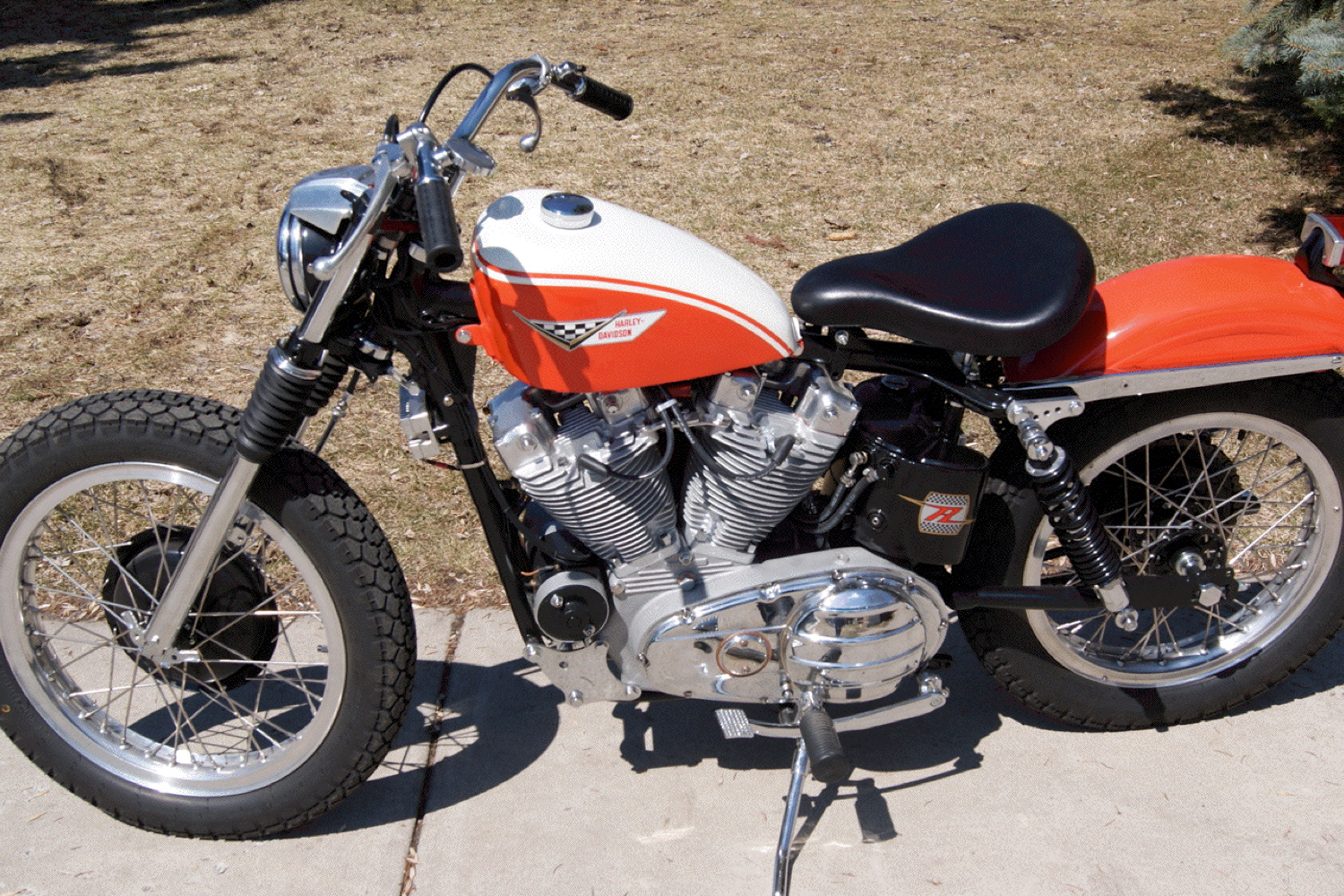
    Kind of an update of sorts. After closer inspection of the oil tank that came with the bike, it's really rough. The threads for all the bungs are crap and cross threaded. And the dude put checker board duct tape on the tank as a "cool custom feature". Which now has the glue almost permanently affixed in a mess to the tank body.

    I gave up on it. Will deal with that tank on the next build. Maybe blast it down to bare metal and retap all the threads. Pain.

    Found a good deal on a brand new CDC tank. Ordered it. Came. Fits. Good to go.

    Now working on finishing the carb rebuild and rework of oil lines, and mounting the new tank. Once I get all that wrapped I'll be able to take some better photos and test run the bike again. More to come.

    Comment

    • bpeak
      Senior Member
      • Nov 2012
      • 553

      #17
      Had a productive weekend on the bike... so several updates and more questions.

      1.) Carb rebuild done. Had a bit of a tricky time with the new leather on the zenith's accelerator pump getting smooth. But got it massaged with some oil and now slides nice. Choke finally works and does its job. It actually holds a tune now. And the float is set right now so no more overflow mess. This was a win.
      2.) New oil tank was fitted nice, I was able to run the hoses too. I chose to eliminate the oil filter and cooler from the loop for now till I know everything works right. Eliminate possible threats. Might add them back in later. But now I officially have supply from tank to pump, return from case to tank, and vent from cam cover to tank. All set nice and tidy. Ran the bike. Checked for return flow and it's pumping good. Faster than before. So whether the vent hose being added did the trick... or the removal of the filter/cooler helped boost return flow... or both... the end result is a win. Also confirmed no leaks from any of the hoses or fittings, especially my stack of brass under the oil tank. I did it this way so that I could have a tee-plug setup for draining the oil tank easier. This tank did not have a drain bung. Just supply. So this helps and will be better than popping off a hose later and trying to control the mess. (I think)

      Click image for larger version

Name:	20180216_160218.jpg
Views:	1
Size:	298.9 KB
ID:	1300741

      Click image for larger version

Name:	20180216_160226.jpg
Views:	1
Size:	302.9 KB
ID:	1300742

      Click image for larger version

Name:	20180216_160239.jpg
Views:	1
Size:	300.3 KB
ID:	1300743

      Click image for larger version

Name:	20180216_160256.jpg
Views:	1
Size:	300.2 KB
ID:	1300744

      Comment

      • bpeak
        Senior Member
        • Nov 2012
        • 553

        #18
        3.) So I decided to start tearing down the bike a bit. Really want to get the chassis mocked. Started taking apart the front end. Noticed that the front top tree was cracked. Right down the middle. Once I got past the hodge-podge of mess the previous owner did with the hand controls and bars, I went to remove the forks. The top tree fell apart as soon as I loosened the last fork tube cap. Insane. Glad I didn't take it for another test ride or two.

        Click image for larger version

Name:	20180218_165046.jpg
Views:	1
Size:	327.3 KB
ID:	1300745

        Comment

        • bpeak
          Senior Member
          • Nov 2012
          • 553

          #19
          But then some good stuff.

          4.) Based on posts here on the ChopCult scene, I was able to follow instructions on heating the neck slightly to tap out the old neck bearing cups. They came out pretty easy with the right heat and a long punch. Was then able to mimic what others have done to build a 'tool' out of threaded rod, washers, and nuts, to press fit the new cups into the frame. Worked like a charm. Nice and even. No hammering. Piece of cake. This is a TCBros neck cup conversion kit for the 1" springer stem. Next up on this front is to pack the bearings with grease, install, and then slide in the springer. I can not wait for this part.

          Click image for larger version

Name:	20180218_165108.jpg
Views:	1
Size:	302.2 KB
ID:	1300746

          5.) Also confirmed true on the front wheel and installed the front tube/tire. 21" 40 spoke spool rim with a dual-sport street legal tire. The placement hold is just a guess for now since the 12+ springer will push the bike up at an angle and who knows how it will really look. After the front end is on, I'll take apart the rear end and prep it for the brand new chrome 18" rear wheel and a bunch of new drum brake parts to totally rebuild the rear stopper. Gonna be sweet. Also tossed on the new gas tank to see the shape. LOVE IT.

          Click image for larger version

Name:	20180218_180921.jpg
Views:	1
Size:	324.4 KB
ID:	1300747

          Comment

          • bpeak
            Senior Member
            • Nov 2012
            • 553

            #20
            But then the drama.

            6.) So after the new carb build, and new oil tank, and new lines, primary empty and refill with the correct fluid, I test fired the bike. Within a minute or two... that same leak started seeping out of the primary filler plug hole. Mind you, this is a brand new filler plug with virgin mesh inside. See back a few posts for the old one and how soaked it was with oil. But again - almost right away, this think started dripping. I tuned the carb a bit, confirmed good oil flow return to the tank, then shut the bike off. Was maybe running a total of 3-5 minutes. Oil oozing out of the filler plug the whole time. As soon as I shut the bike down, I pulled the primary filler plug hoping to find an answer. But the primary fluid level was perfect. Way down in the case where it should be. The primary is NOT "full". So what gives? For oil to seep out that quick... there has to be a TON of oil slinging when the primary chain is whippin. But that wouldn't be enough on its own to leak that bad right? The only other thing I can think is that the primary is under some serious positive pressure and the mist/air/oil is trying to escape.

            I confirmed again that the dreaded transfer valve IS BLOCKED OFF with what looks to be JB Weld.

            No other real noticeable primary leaks or cracks or troubles - although I have not yet pulled the primary cover to fully inspect.

            The only other thing I can think is what I'll post in the next reply... regarding the cam/gear cover on the other side of the motor.

            Comment

            • bpeak
              Senior Member
              • Nov 2012
              • 553

              #21
              7.) Here's the deal. I started looking around the rest of the engine and noticed even more eyebrow-raising stuff. On the cam cover, check out these photos... keeping in mind that this is a '71:

              Click image for larger version

Name:	20180219_061714.jpg
Views:	1
Size:	292.0 KB
ID:	1300748

              Click image for larger version

Name:	20180219_061738.jpg
Views:	1
Size:	294.1 KB
ID:	1300749

              Best I can tell from 1971 - the bottom 6 o'clock off the genny should be just a breather tube. I confirmed that this is the squared off oil pump... so it should have the timed breather and therefore just needs a breather tube (no foo foo valve) off the generator housing. There shouldn't be anything off the top of this cover (12 o'clock position) should there????

              I removed both the 6 and 12 o'clock fittings. This is the top one (looks home-drilled-tapped... can't be factory right?):

              Click image for larger version

Name:	20180219_062707.jpg
Views:	1
Size:	290.5 KB
ID:	1300750

              This is the bottom - which looks correct, going up to the air/oil separator gyro at the end of the genny:

              Click image for larger version

Name:	20180219_062944.jpg
Views:	1
Size:	293.0 KB
ID:	1300751

              And this is the thing I took out. No idea what it is. Possibly a foo foo valve that is missing parts? Whatever it is, the black part was caulked/sealed/painted so many times it's solid. Almost has a hex allen wrench style fitting in the bottom black area. But it is solid. No venting or air/fluid passage through this thing.

              Click image for larger version

Name:	20180219_063043.jpg
Views:	1
Size:	312.8 KB
ID:	1300752

              I have a feeling that the previous owner blocked off the bottom one or tried a foo... didn't work... and one night late after some beers they decided to drill a new vent in the 12 o'clock position? The top vent is just a raw tee fitting with a hose. No backflow or valve.

              But for this breather to actually WORK on a '71... it has to come from the bottom right? Cause that's where the separator is inside? Or am I backwards?

              I guess this is my root questions:

              A) would it be best to get a stock breather valve for the 6 o'clock and seal off the top one with a solid bolt?
              B) if what they did IS ACTUALLY wrong... could that be causing weird pressure differences and be the suspect for why the primary side is somehow over pressurizing... causing the leak out the primary filler plug?

              I know this is a LOT of info and too many questions. But I'm struggling to make sense out of a bike that was clearly hacked together.

              Any help you guys could offer would be most excellent. Thanks in advance.

              Comment

              • TriNortchopz
                Senior Member
                • Dec 2017
                • 3256

                #22
                Here is info from XL Forum member, Hopper, which may be helpful;
                Engine breather 101 / Crankcase vent 101

                WHAT IS IT?
                The engine breather, or crankcase vent as Harley sometimes calls it, is to allow air out of the lower crankcase, but not in, as the pistons rise and fall. Without some kind of controlled breather, the lower end would become a 1,000cc air compressor, robbing the engine of several horsepower. Old time tuners like Jerry Branch, Tom Sifton and Dick O’Brien paid much attention to the engine breather because they knew it could give them extra horsepower if set up right.

                One thing not to do with an engine breather is to simply plumb a hose to the crankcase without some kind of one-way valve or timed breather valve. It is commonly done, but it wastes power and is not good for your engine.

                WHERE IS IT?

                Pre-1977
                There is a timed breather valve built into the oil pump drive, which vents crankcase pressure into the cam timing chest. A six-inch metal tube hanging down from the timing cover near the generator drive, at the 6 o’clock position vents that controlled pressure to atmosphere. A metal disc on the end of the generator drive gear centrifugally separates oil from the air as it is discharged overboard.

                LINKS
                Discussion on foo-foo valves and engine breathers pics etc here:


                See thread here: http://xlforum.net/vbportal/forums/s....php?p=1960632

                Here is some interesting info for Sportsters from Texas-based IronHeadCycle, including Frequently Asked Questions With Answers, and 7 chapters of instructional on building the Sportster(though not directly related to your breather Q):
                Last edited by TriNortchopz; 02-19-2018, 7:23 AM. Reason: added IronHeadCycle link
                If buildin' old school choppers was easy, anyone could do it... ain't nobody said it's gonna be easy...

                Comment

                • bpeak
                  Senior Member
                  • Nov 2012
                  • 553

                  #23
                  Awesome thanks for the link and info. I spent a few hours last night reading up on all the major forums on this topic. Definitely seems as though the way this bike was set up is not right. So I'm going to try to make it right. Ordered the $14 solid breather tube for the 6 o'clock position and will get a plug for the top fitting the P.O. drilled in. The question then becomes... did the P.O. do this because of some other problem? Makes me wonder about the status of the oil pump and oil pump timing. I do have an oil pump rebuild kit for the bottom end of it. When the motor comes out of the frame for paint, I might try to pull the cam cover and verify the oil pump timing and do the rebuild. I have no idea if this will have any impact on the primary side filler plug leak. But getting it all done right can't hurt. I hope. Ha.

                  Comment

                  • bpeak
                    Senior Member
                    • Nov 2012
                    • 553

                    #24
                    In the meantime... spent some time last night mocking up the roller. Had to see some progress. Been waiting for months to put this springer on.

                    Click image for larger version

Name:	20180219_165931.jpg
Views:	2
Size:	313.4 KB
ID:	1300789

                    Click image for larger version

Name:	20180219_170013.jpg
Views:	1
Size:	310.0 KB
ID:	1300790

                    Click image for larger version

Name:	20180219_170025.jpg
Views:	1
Size:	309.1 KB
ID:	1300791

                    Click image for larger version

Name:	20180219_170405.jpg
Views:	1
Size:	317.0 KB
ID:	1300792

                    Comment

                    • bpeak
                      Senior Member
                      • Nov 2012
                      • 553

                      #25
                      Ugh... the hits keep coming. There are at least two major problems in this photo that I found this morning. 10 points for the first to notice. 100 points to the first to tell me the best way to fix them.

                      Click image for larger version

Name:	20180125_061721-1.JPG
Views:	1
Size:	203.8 KB
ID:	1300840

                      Comment

                      • Dragstews
                        Senior Member
                        • Sep 2010
                        • 13739

                        #26
                        What in the world is going on with the rear mount ... ???
                        And where did the dowel pin go for the kick cover ... ??

                        Click image for larger version

Name:	20180125_061721-1.jpg
Views:	1
Size:	292.4 KB
ID:	1300851

                        Let's Pow-Wow some on what I see ....

                        First arrow Top left:

                        Stud snapped off .... That's going to be a booger to get out of the case... Going to need to pull the motor for that repair.

                        Second Arrow down from dat:

                        Holy Mowly ... Looks like the kick shaft case hole been welded up... If so ... Case will need to be stripped down to bare nothing and major machine work done...

                        Arrow below that one ... Rear mount is toast .... After/market has a H-D replacement,


                        Right side arrows:

                        Dowel missing, easy fix..

                        Speed-do hole needs to be welded up and the counter shaft bearing case bore beefed...
                        Last edited by Dragstews; 02-23-2018, 6:51 AM.
                        Take my 45 and outrun em all ..

                        Comment

                        • bpeak
                          Senior Member
                          • Nov 2012
                          • 553

                          #27
                          Yup. That pretty much sums it up. I hadn't yet researched that bottom area for the dowel and Speedo deal so thanks for the head-start.

                          Yea so yesterday I spent a ton of time online on this motor mount and watched a few hours of Tatro's YouTube channel. I like the one you posted a pic of - the pingel - because the stockers require splitting the case right? I really don't want to split the case just for the motor mount. But that pingel should slide right on. More expensive but will save time and money overall. Plus it's super reinforced. Cool stuff.

                          I'm still investigating the stud that broke off. I do plan on pulling the motor out later... and I've read up on it a bit. Gonna have to really set aside time for that task and be careful I guess. Here to... hoping that problem doesn't force a case split.

                          On the kicker shaft, I'm going to inspect the welds when I have the motor out. If it's truly sealed up solid, then I'm going to leave it. I have the e-start. Would love to have the kicker too but I'm getting a bit $$ shy thanks to all the hack-jobbing that I'm finding on this donor.

                          Course then again... I might have to bite the bullet and take the motor to a shop to be fully rebuilt. That will take a lot longer to get back on the road (financially) but shoot... if this kind of work is what I'm finding on the outside, what in the world is on the INSIDE of this motor?

                          Comment

                          • Dragstews
                            Senior Member
                            • Sep 2010
                            • 13739

                            #28
                            The Heavy Duty mount does install without spiting the case...

                            Your broken stud may be R&R-ed with the use of a Snap-on roller clutch stud remover tool, may see the need to heat the case up..

                            If your not going to fix the case kick shaft hole, the dowel pin won't be needed.

                            There is a way to beef the counter-shaft case bearing bore without welding the speedo hole up...
                            Basically a ring is made up to press over the shoulder and then using the speedo driven gear with a taper ground to the gear installed under the pressed on ring in turn pushing up on the ring.... Granted it's not as beefy as welding, but is a heiiofa better off than leaving it stock....
                            Take my 45 and outrun em all ..

                            Comment

                            • bpeak
                              Senior Member
                              • Nov 2012
                              • 553

                              #29
                              Dragstews... shoot man - I just realized that we live 1.5 hrs away from eachother (if your profile is up to date). Dude... I'm gonna owe you some beers here in Tampa before this thing is over.

                              On the mount - I'm definitely good with the pingel for sure. Best I've found is about $160 on eBay. Pricey but worth it all things considered.

                              On the speedo - I'm considering just removing the drive and plugging the hole with the colony plug/bolt/washer kit. Concerns?

                              And one final laugh for the morning - I checked the front motor mounts. The dude has those cobbled together too. Washers and spacers where they shouldn't be. The right side plate is cocked at an angle as a result. And the one top front stud to the frame was loose with center spacers that weren't the right length. Haha. AWESOME. Another part to replace.

                              So with a half way loose front motor mount, a rear motor mount that was only the bottom two studs, and no top motor mount at all... no wonder thing thing vibrated like crazy. Holy cow.

                              I have officially jumped right past the "forget this crap I'm bailing on this bike" stage and landed right in the "I'm now on a crusade to save this bike" mindset. I have to save it. It's up to me. The shop I bought it from was honest that it had problems and sold it to me for a fair price (I can say that now still - it was fair). But in the hands of someone else - they might have given up on it by now and it would have ended up getting parted out or parked in a garage for another decade. Not me. It's my baby now. Gotta make it right and save this 47 year old monster.

                              Comment

                              • FatChibs
                                Senior Member
                                • Feb 2014
                                • 705

                                #30
                                jfc cant believe someone welded up the kicker shaft hole....thats nasty.

                                Comment

                                300 mobile ad bottom forum

                                Collapse
                                Working...
                                ;