'95 Sportster build

Collapse

Desktop Ad Forum Top

Collapse

Mobile ad top forum

Collapse
X
 
  • Time
  • Show
Clear All
new posts
  • industrialmarshmallow
    Member
    • Aug 2017
    • 88

    #16
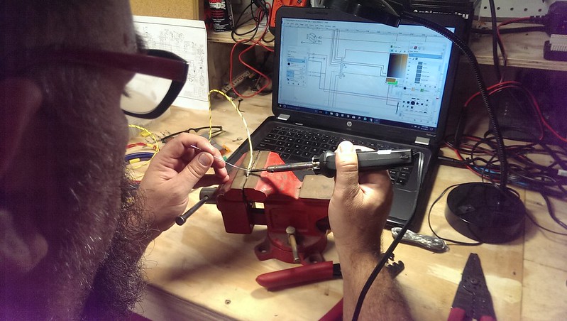
    Spending much time staring at the stock and M-Unit wiring diagrams. Planning a harness takes a lot of thought before you even touch wire and that goes double for an M-Unit because it's so different. One of the Revival Cycles guys said, "If a stock headlight switch functions essentially like a household light switch, the same physical switch in an M-Unit setup functions like the enter key on the keyboard of the PC you're on right now." And that's really the best description.

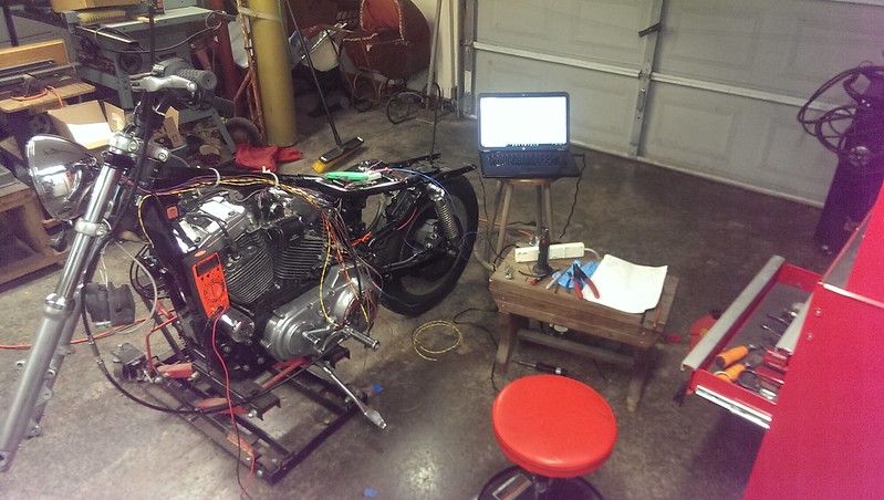
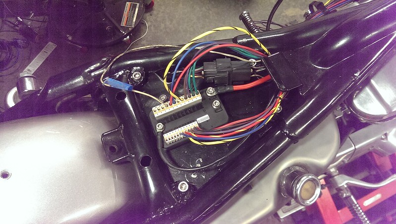
    After studying and studying those diagrams and watching and rewatching every YouTube video on M-Unit and Harley wiring stuff I could find I set up a bench testing station to check connections before I started putting wire back on the bike.

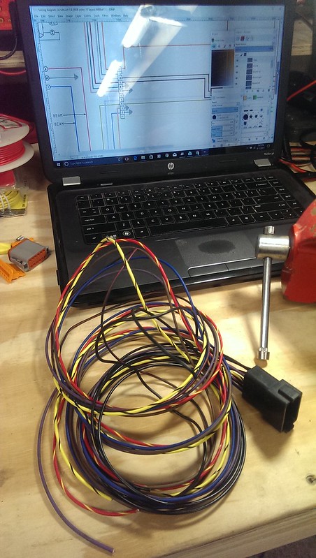
    I scanned in the stock diagram and used a free online image editing program named Gimp to cut it up into pieces. I got rid of what I didn't need and kept what I did. I created "groups" for the various circuits, Left grip switches, right grip switches, left turn signals, right turn signals and so on. I organized it into "layers" (anyone who has worked with Photoshop or other similar image editing software will be familiar with layers) so I could make changes without affecting other groups. This also makes it easy to turn visibility off and on and move groups around the page individually.

    I'm planning on posting the finished diagram, but not until after everything is installed and tested. I don't want to put bad info out there. Also, even though some wire colors will be the same, this diagram will bear no resemblance to the stock one at all with regards to how things flow so it will really only be useful if you are installing an M-Unit.

    I have had a couple times where I got stuck on a circuit and had to shoot an email to Revival Cycles tech line and get bailed out. Jeff and Stefan there have been nothing but patient, helpful and cool. I can't thank those guys enough.

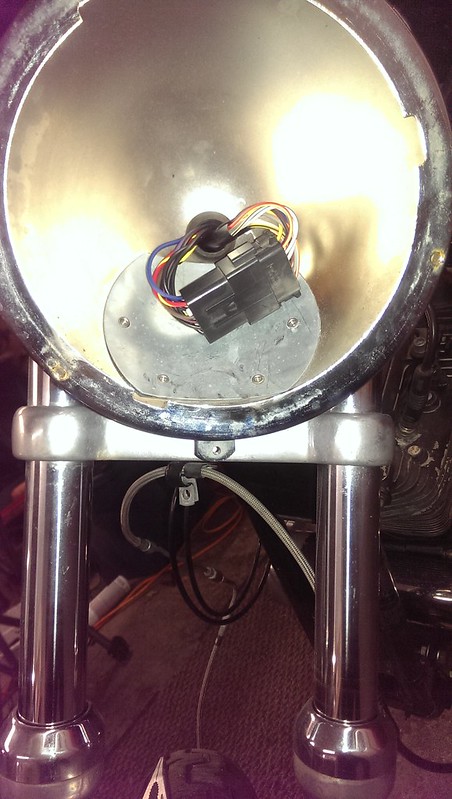
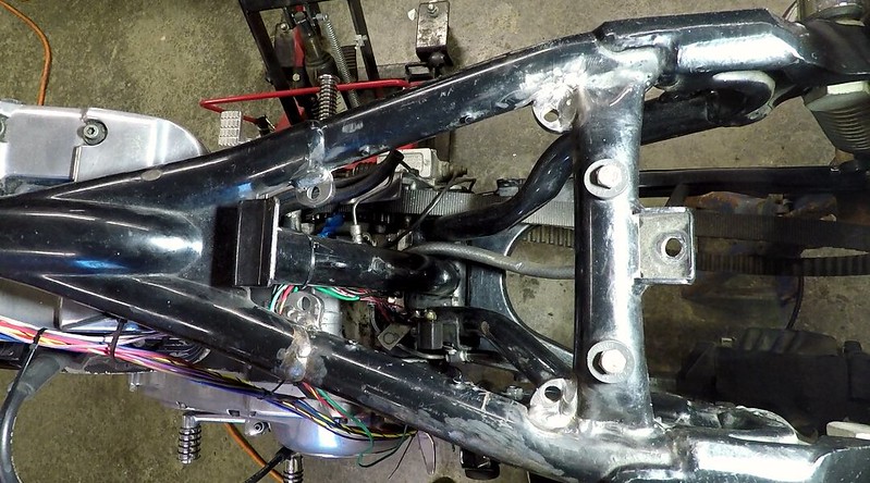
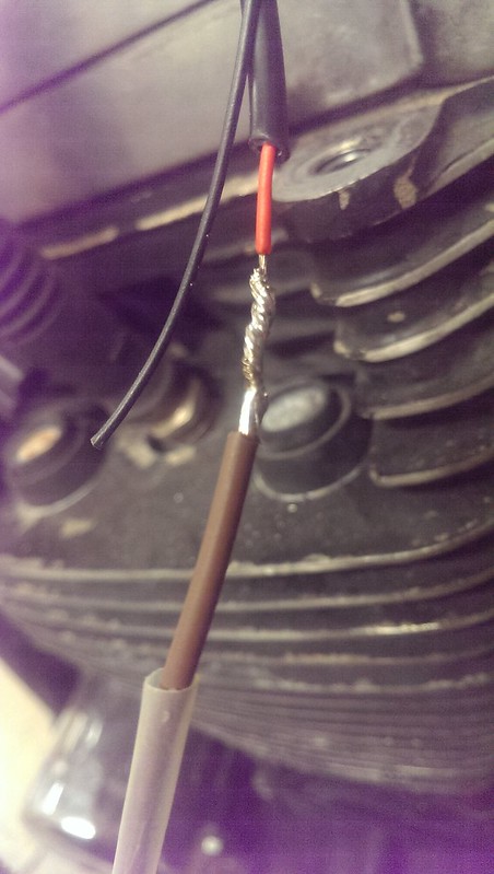
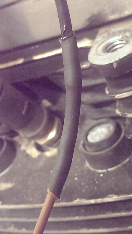
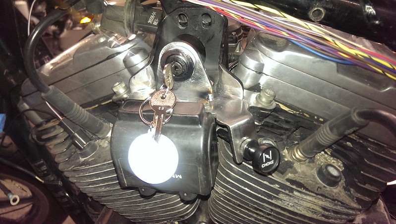
    I reused a stock Deutsch connector to connect the bar control switches to the
    wires that run back to the M-Unit inputs. I used open barrel pins and soldered after I crimped.

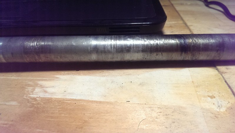
    IMAG2207 by David Arens, on Flickr

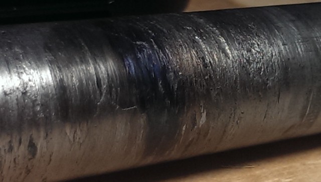
    IMAG2208 by David Arens, on Flickr

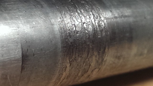
    IMAG2210 by David Arens, on Flickr

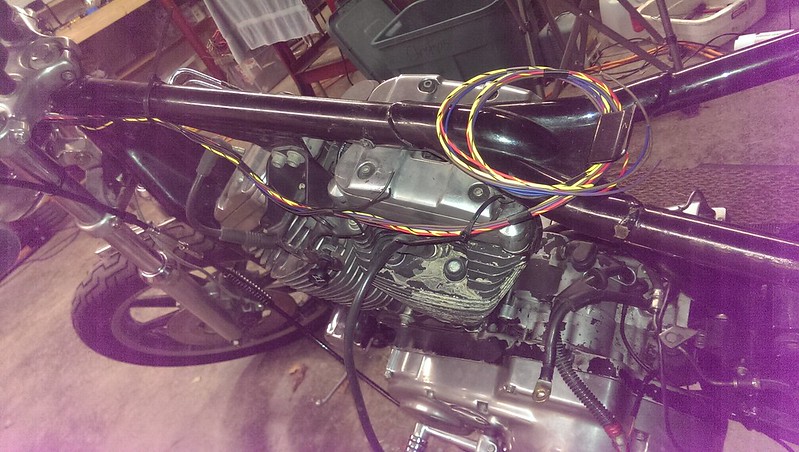
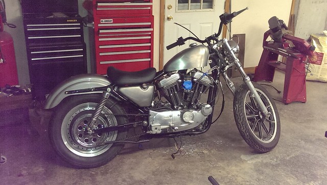
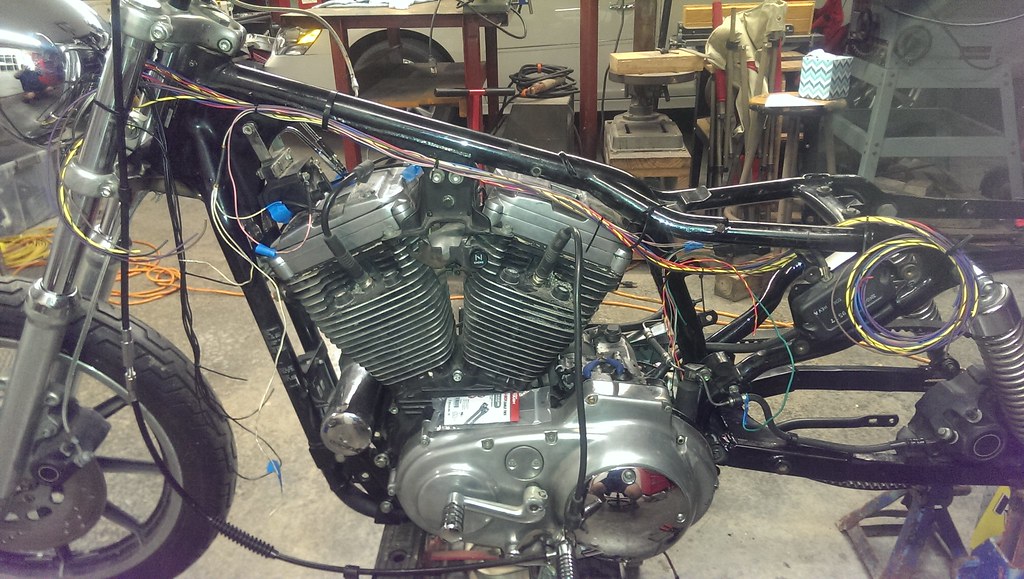
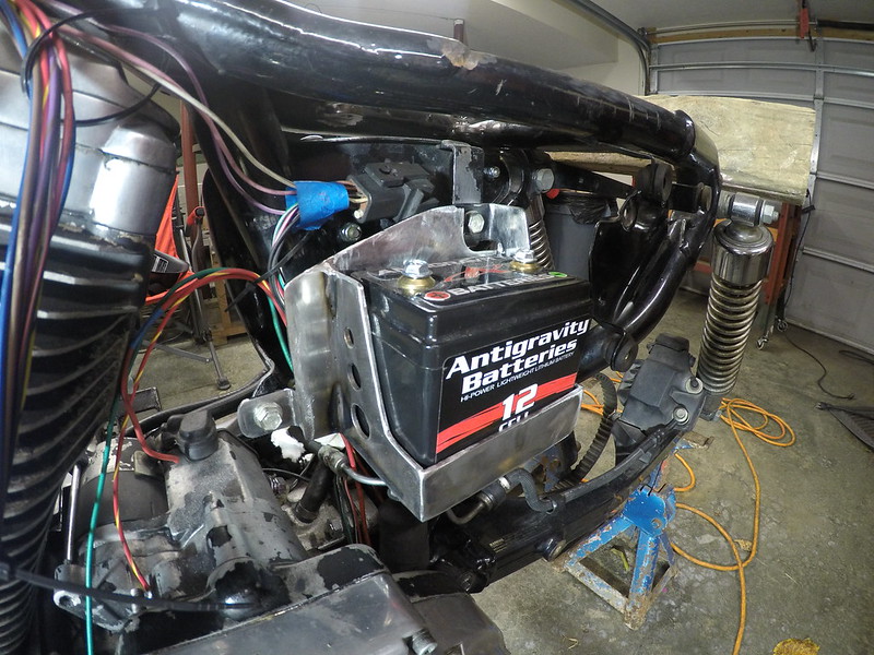
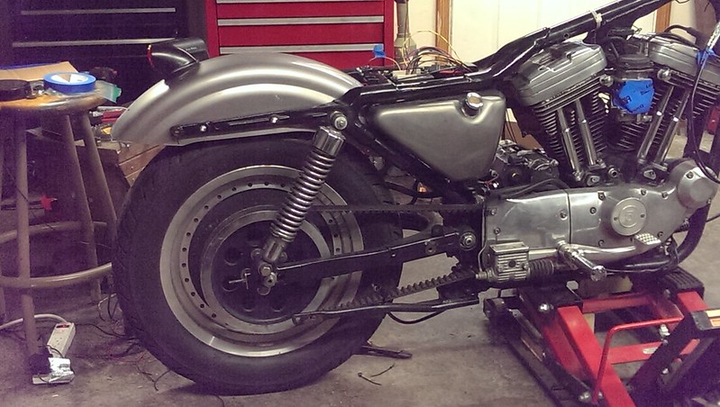
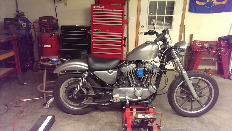
    Just mocking it up for length, but it's nice to be putting wire back on the bike.

    IMAG2211 by David Arens, on Flickr

    Comment

    • Dougtheinternetannoyance123
      Senior Member
      • Apr 2012
      • 1021

      #17
      Could be a cool scooter, I have a 98 in similar condition I bought a couple years back to replace my daily rider that got Smooshed into a hood ornament,, I started hanging parts on it to sort it out, and need to do exactly the same thing. Plan is to get all the parts back where they belong and working, then tear it down for the build.
      Street tracker with some upgrades is the plan. Been stockpiling parts for the last 2 years and getting the workshop back to functional.

      Best of luck with the build.

      Comment

      • industrialmarshmallow
        Member
        • Aug 2017
        • 88

        #18
        I've reached the point where I have to make some kind of platform for the M-Unit to mount to under the seat. Since I'm using the new M-Unit blue the wires connect vertically into the top of the unit, not into the side like the earlier model. This means that you have to be very aware of how much clearance you have above the M-unit. In order to figure that out I needed a seat.
        The seat I "want" is one of the Biltwell models, either the Cafe or Banana but they run close to $200 and I don't want to spend that kind of $$ on a seat while I have so much other stuff I need to finish on the electrics. I ended up finding a stock solo seat on CL in new condition for $35 which was just what I needed. A plus was talking to the older guy who listed it. He had ridden his Electra Glide through the lower 48 and up to Alaska, then flew down to Hawaii and rented a bike just to say he had ridden all 50.

        As a matter of fact just about everyone I've bought parts from or sold parts to on CL has been cool and we've ended up just talking bikes for a lot longer than it takes to make the transaction.

        Anyway... Using the seat I was able to build a pan to use as a mounting surface for the M-Unit. It's going to be tight, but it will clear. I'm using a piece of 1/8" sheet so I can tap it for the mounting bolts.

        I need a few more parts to finish up the electrics. Ignition switch, front indicators, tail/stop light and a couple other things. In order to fund that stuff, I'm listing the rest of the chrome covers on CL. Today I removed the rear wheel so I could get the chrome pulley cover off. Getting the axle out was a giant PITA and once it was free I can see why. It's pretty gouged up on the bearing surfaces and it looks like one spot has been hot enough to color. I haven't pulled the bearings (don't want to get sidetracked off the electrics) but my guess is that they aren't too healthy.

        IMAG2287 by David Arens, on Flickr

        IMAG2285 by David Arens, on Flickr

        IMAG2286 by David Arens, on Flickr

        Seat
        IMAG2238 by David Arens, on Flickr

        Comment

        • industrialmarshmallow
          Member
          • Aug 2017
          • 88

          #19
          Added a few more circuits. When wiring an M-Unit you have to remember that each circuit usually consists of an input wire with an accompanying ground, an output wire to the component, and then in most cases another ground. So in even a very simple circuit like the horn (remember, I used the stock handlebar controls and switches) you have the horn input wire running from the switch to the horn input on the M-Unit. Since I'm mounting the unit under the seat, that's one wire running from the
          grip to a deutsch connector in the headlamp housing, then down the frame backbone to under the seat. Then, I'm using the orange and white wire as the ground side of the horn switch and it runs from the switch to the deutsch connector in the headlight bucket and then down to where I'm going to ground it at the upper front motor mount.

          That's the input side of the circuit. The output side has a wire running from the M-Unit horn output back up the backbone to the horn "+" and then a wire from the horn "-" to a ground.

          While I think the M-Unit is really very simple to wire, using it like I am with the stock controls uses quite a bit more wire than using the Motogadget control buttons or a Motogadget "M-Button".

          IMAG2302 by David Arens, on Flickr

          Comment

          • industrialmarshmallow
            Member
            • Aug 2017
            • 88

            #20
            I finally got to a point where I was going to have to make some stuff before I could go any further. I decided to cut out a plate to fit under the seat. This is where the M-Unit and main circuit breaker will mount and will also serve as kind of a main junction area for all the wire. I used 1/8" sheet for this so it would be stiff and have enough meat to hold threads. Cardboard from the back of a notebook was used to make a pattern and the steel was cut with an angle grinder loaded with a cutoff disc. I had to grind a little to clear one of the ignition
            module mounting tabs.

            I used a piece of 1/4" thick by 1" bar stock to make 4 tabs. After grinding the paint off the frame and tacking the tabs in place I drilled holes slightly larger than the 5/16" x 3/4" allen head bolts. I wanted to end up with a 5/16" drill but somehow bent the one I had when it got jammed making the first hole. So I used some oddball bit I found that was just a gnat's ass bigger. I drilled the holes in steps so before I got to the final size I clamped the plate in position and used the tabs as a template to mark it with a transfer punch.

            I drilled the holes in the plate using a 17/64 drill which Home depot only had as either part of a $60 bit set or as a bit/tap combo.
            This forced me to buy the combo which aggravated me because I already had the tap at home. After tapping the holes to 5/16-18 and test fitting, the holes in the plate were out by about 1/16 which caused it to bind when I torqued it down. I said "Fudge".

            Since the tabs were still just tacked, I figured it was easier to move the them than the freshly drilled and tapped holes in the plate. I broke the front two tabs off and ground the tack welds down. I then mounted the plate to the frame using just the two rear tabs. I mounted the two front tabs to the plate using the bolts to locate and then clamp them. If that was where they wanted to be that's where I'd put them. I clamped the front of the plate tight, re-tacked the tabs and made sure there wasn't any more binding. Once I was sure, I went ahead and fully welded them in. Luckily, the really crappy looking beads are on the underside.

            I figured out where the M-Unit would be located and used a transfer punch to mark the two mounting holes. Then drilled (I think using a #16 drill) and tapped for the M5-08 threaded allen head mounting screws included with the M-Unit.

            2017-10-16_09-32-41 by David Arens, on Flickr

            2017-10-16_09-33-00 by David Arens, on Flickr

            Comment

            • industrialmarshmallow
              Member
              • Aug 2017
              • 88

              #21
              Since I'm running an Antigravity 12 Cell lithium battery, it's quite a bit smaller than the stock one. I decided to resize the battery box instead of using the filler padding that came with the battery. Using the battery itself as a template, I drew around it with a silver sharpie. I knew I wanted to keep all three mounting points. Essentially, I would cut off the left side (saving the full back) and about an inch or so all the way across the front.Initially I thought I could keep the left side and just re weld it further to the right, but due to the way the left side mounting point is constructed this proved to be impossible and I had to cut a whole new piece.

              I had to cut a rectangular filler piece for the bottom after I squared up the remains of a round hole that was there and then cut a new front. I used 1/8" plate for this as it was a pretty close match in thickness to the stock materiel. Again, I used a angle grinder and cutoff disc to make the cuts. It looked like it would be a PITA to match the stock cutout in the side panel with the tools I have so I drilled go fast holes instead and I actually like them better.

              I just need to decide on a hold down mechanism of some kind. I keep going between painting it black or using some kind of "rubberized" coating. I'll probably end up painting it.

              2017-10-16_09-16-01 by David Arens, on Flickr

              GOPR0014 by David Arens, on Flickr

              2017-10-16_09-16-31 by David Arens, on Flickr

              IMAG2321 by David Arens, on Flickr

              GOPR0026 by David Arens, on Flickr

              Comment

              • WillSCB
                Senior Member
                • Dec 2014
                • 442

                #22
                Just spotted this thread, and going to keep an eye on it. Looks good so far. One question I have is regarding the "m-unit." I am not familiar with this set up. What are the advantages? As soon as I saw the wire nuts on the old wiring, I figured it would be easier just to rewire it from scratch. Anytime I see wire nuts (or gobs of silicone as this one had) on a vehicle, I assume the previous owner either had to make some roadside fixes using Home Depot supplies, or just flat out had no idea what he was doing, and just scrap everything and start from scratch. Keep us posted, and more info about the m-unit would be appreciated.

                Comment

                • Dougtheinternetannoyance123
                  Senior Member
                  • Apr 2012
                  • 1021

                  #23
                  The M units are being used on a lot of custom builds, IE, mutant Buells, Cafe racer BMWs and Sport bikes.. they are interesting setups and allow a very minimalistic style switchs. Some parts of it are super cool, but at the same time some of it is kinda out there.

                  But in this case, the OP is only using part of their wiring setup and that to me is interesting how he is going to make it all work.
                  Ive always wired up MCs original or slightly modified and a few relays thrown in, but nothing too exotic. But this should be interesting how he pulls it all off.

                  See: https://motogadget.com/shop/en/m-switch.html

                  If you look around, a lot of custom builders are using these. Theres a cool Buell build that I followed on another forum.
                  Theres lots of builds using them,

                  (One example See: http://www.badweatherbikers.com/buel...tml?1497902557 )

                  Comment

                  • industrialmarshmallow
                    Member
                    • Aug 2017
                    • 88

                    #24
                    You have to unlearn a lot of what you know about 12v electrics to wrap your head around the MotoGadget M-Unit. If you think of a traditional 12v circuit as operating like a light switch in a room, think of an M-Unit as a keyboard on your computer. In a typical M-Unit circuit, a switch doesn't really carry any current. One side connects to an M-Unit Input and the other side connects to ground. When you hit the switch, the M-Unit reads that change as an input signal and performs whatever action you have programmed it to do. So hitting the horn button doesn't send 12v to the horn, it tells the M-Unit to send 12v to the horn.

                    Like Dougtheinternetannoyance123 said, I'm using the stock controls which is kind of a PITA. Using the MotoGadget controls would have made this a lot easier. The trouble with the stock controls is that one side of the switch has to go to ground and they just aren't set up that way from the factory. I'm also not running any gauges or idiot lights which made things a little easier.

                    Revival Cycles has some pretty good videos on it on Youtube.

                    I created this diagram by reworking the stock one out of the '95 Factory Service manual. I scanned it and used "Gimp" image editor (free Photoshop knockoff from the web) to cut all the circuits into different layers and delete everything I wasn't using. I wasn't going to post it yet, because I haven't tested the start and charging circuits yet but I figure I'll throw it up with this disclaimer: THIS DIAGRAM IS A DRAFT COPY AND HAS NOT BEEN FULLY TESTED ON A RUNNING BIKE. I am posting it only to illustrate how M-Unit circuits work with stock controls and not as a blueprint for someone else's install. I have tested the horn, running light, brake light, indicators and headlight circuits and they work.

                    Click image for larger version

Name:	Munit.jpg
Views:	2
Size:	290.5 KB
ID:	1298440

                    Comment

                    • industrialmarshmallow
                      Member
                      • Aug 2017
                      • 88

                      #25
                      Progress is slow, but I recently sold the last of the chrome covers that came on the bike so that gave the project a much needed injection of funds. I've been collecting a few parts here and there and am waiting on a Biltwell Mako tail light to come in (Thanks Lowbrow Black Friday sale!)so once I get that and an ignition switch tab that should be in the same order I'll be back in business.

                      In the meantime, I had to tweak the battery box in order to make a hold down I was happy with. I didn't want it to be overly complicated so ended up cutting the heads off a couple of 5/16 bolts and welding them upside down on the sides of the box. Then I used a piece of 1 inch by 1/4 bar as a hold down. Right now it's held on by wing nuts because I like the way it looks but I don't trust them and will be watching close should they decide to betray me.

                      Unfortunately, in order to do it that way I had to trim the right side down even with the left. Which meant I had to take off one side of the top right mounting tab. If you compare the picture I already posted and this one you should be able to see what I mean. I think it'll be OK, it still mounts using all three original holes and the battery weighs a hell of a lot less than it used to.

                      The other thing I'm working on is adding a coil mount and ignition switch mount to the stock top motor mount. I also had to relocate the choke mount. I know, that's a lot of mounts. I'm waiting on the ignition switch tab to finish that up. I had actually ordered a new top motor mount with coil and ignition mount from Gasbox but when it came and I compared it to the stock mount it just didn't seem as beefy. I'm sure it would have been perfectly adequate, but I was going to have to add the choke mount anyway and it wasn't much more work just to modify the original one. So I sent the Gasbox one back and put the $75 towards a set of Joker Machine fork mount front signals.

                      So once I get the ignition switch tab welded up, I have a horn, front signals, ignition switch, and tail light ready to go. Still on the fence with using the original rear signals or waiting longer to save up for some nice LED units. Oh, I also installed a Speedo sensor block off from James Gaskets. It's a heavy duty plastic and comes with hardware for under $10. I canceled the metal one I had backordered at Lowbrow, it was $25 and some reviews said the plastic one sealed better anyway.

                      IMAG2361 by David Arens, on Flickr

                      IMAG2352 by David Arens, on Flickr

                      Comment

                      • afraziaaaa
                        Senior Member
                        • Jul 2012
                        • 296

                        #26
                        You're really resurrecting that monstrosity. Nice work. I like what you've got going on with the wiring and the mounts so far.

                        I made my own speedo sensor delete with a pair of scissors...

                        Comment

                        • industrialmarshmallow
                          Member
                          • Aug 2017
                          • 88

                          #27
                          Thanks! And how did you get those scissors to seal?

                          Comment

                          • afraziaaaa
                            Senior Member
                            • Jul 2012
                            • 296

                            #28
                            Originally posted by industrialmarshmallow
                            Thanks! And how did you get those scissors to seal?
                            Hahaha. I probably should have just spent the $10 instead of cutting the wires off.

                            Comment

                            • industrialmarshmallow
                              Member
                              • Aug 2017
                              • 88

                              #29
                              Two months since my last update... I was visiting family out of town over the holidays and then, three weeks ago, I was checking my patio to see if it was icy. It was. The broken kneecap slowed me down for another week or so but by far the thing slowing me down the most is routing this wiring harness. I've had to redo several connections because I cut them too short or decided to reroute after I had already terminated it, or like the coil leads, I did them the first time with ring terminals that were a little too large because that's what I had on hand and it just kept bugging me until I redid them with the right size. I've also had to research different types of loom until I found something I think will work, plus saved enough change to buy misc stuff like the loom, loom tape, bullet connectors, shrink/adhesive ring terminals, more double wall adhesive shrink tubing, clear shrink tubing, 40amp circuit breaker etc... etc... Whcih all adds up after a while.

                              Anyway, I can see the taillight at the end of the wiring tunnel. I have some work to do on the connections from the main circuit breaker, and I haven't touched the taillight and rear turn signals yet, especially since I'm not sure if I'm keeping the stock signals or not and still I have to strip and trim the rear fender. Oh, and then loom everything. But assuming ( I know) that everything works, that's about it for wiring.

                              IMAG2422 by David Arens, on Flickr

                              While I'm here, I'll just mention some of the methods I've used to make connections. I've re-used some of the stock Deutsch connectors in places. When using those, I've crimped and soldered the little pins. I've used crimp and shrink ring terminals and I will usually use black shrink tube over that for added protection. Also, I think it gives the connection a good clean look. For most connections I'll use the double wall adhesive stuff.

                              For the horn, I used plastic covered crimp on female blade connectors with shrink tube added over the crimp part. I soldered some connections (like led turn signals) because the wires were so small I wasn't sure a butt connector would work when connecting to the 14/16 ga wire in the harness. When I did those I twisted and soldered the wires, then shrunk a piece of small diameter shrink tubing over the connection, then over that, a larger piece of adhesive shrink tubing. I'm hoping that gives the connection enough strain relief that vibration won't bother it. I've read that solder connections can be too brittle for bikes. I guess I'll find out.

                              Another place I soldered connections was where I had to join a wire to the middle of another wire. I stripped an inch or so of the wire by using a typical wire stripper to ring the insulation at both ends of the inch, then a razor knife to cut and peel it off exposing the copper. Then it was twist, solder and shrink as above.
                              IMAG2380 by David Arens, on Flickr

                              IMAG2381 by David Arens, on Flickr

                              IMAG2383 by David Arens, on Flickr


                              As far as real work, I got the key switch tab welded on the motor mount and I'm happy with it. It's still just tacked in the picture, and I ended up cutting a little off the bottom to shorten it some before I fully welded it.

                              IMAG2373 by David Arens, on Flickr

                              Comment

                              • industrialmarshmallow
                                Member
                                • Aug 2017
                                • 88

                                #30
                                Over this past weekend I was able to do a bunch of little stuff that needed doing. I have pretty much all of the inputs and outputs connected to the M-unit except one. At this point they aren't trimmed to the final length, I'm going to wait to do that until I test everything and am doing the looming.

                                I needed to wire up the tail light, but before I could do that I had to figure out placement and before I could do THAT, I had to cut the fender. I lot of the cut fenders I looked at seemed to be cut at 45deg or so and I was all set to do it that way. But after messing around with tape and cardboard for a while I decided to go with a more subtle trim. I like the way it looks, it's different than most of the cut fenders I see, and if I decide to cut more in the future I can. I'm also keeping full struts. For now anyway...

                                That allowed me to mock up the Biltwell Mako tailight, which I decided looked good pushed rearwards just slightly past where the lens would be vertical.

                                I still need to strip the paint off the fender, weld up some holes and make some new ones. I'm planning on a bare metal finish and I'm wondering if the black Mako will look like a big ass wart on the bare metal fender. I guess we'll see. I can always strip that too.

                                The next thing is turn signals. I kept going back and forth with running the stock ones, but I've decided to go with some LEDS. A quality set will add time and money, but I won't hate looking at them.

                                IMAG2438 by David Arens, on Flickr

                                IMAG2437 by David Arens, on Flickr

                                IMAG2440 by David Arens, on Flickr

                                Comment

                                300 mobile ad bottom forum

                                Collapse
                                Working...
                                ;