Evo Sporty Rewire (Reduced to Essentials Only)

Collapse

Desktop Ad Forum Top

Collapse

Mobile ad top forum

Collapse
This is a sticky topic.
X
X
 
  • Time
  • Show
Clear All
new posts
  • billdozer
    • Apr 2024

    Evo Sporty Rewire (Reduced to Essentials Only)

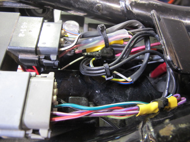
    One of the common questions I hear quite a bit is "How do I get rid of all the bullshit wiring on my Evo Sportster"?

    It's really not rocket science, especially on earlier ones but it can be intimidating to hack up the bundle of perfectly operating wires just for the sake of getting the bare-bones aesthetic.

    For this thread we are using BF Josh's 2002 Sportster "S" model with dual plug heads. Other models and years will vary, but the concept will be the same. If you asked ten people how to do it, you'd probably get twenty answers, this ain't gospel, it's just the way I did it. And it worked, has way less snarl of an unsightly harness, especially now that more of the bike is exposed with a flat bottomed tank, fiberglass tail section, etc.

    On Josh's stock bike there were no fancy sensors or other "nanny" switches that needed to be looped or disabled. This may be the case on later model bikes. We ditched the VOES petcock for an old Pingle one, and capped any open vacuum connections on carb or manifold with high quality rubber caps.

    Factory 2002 Sporty Wiring Diagram

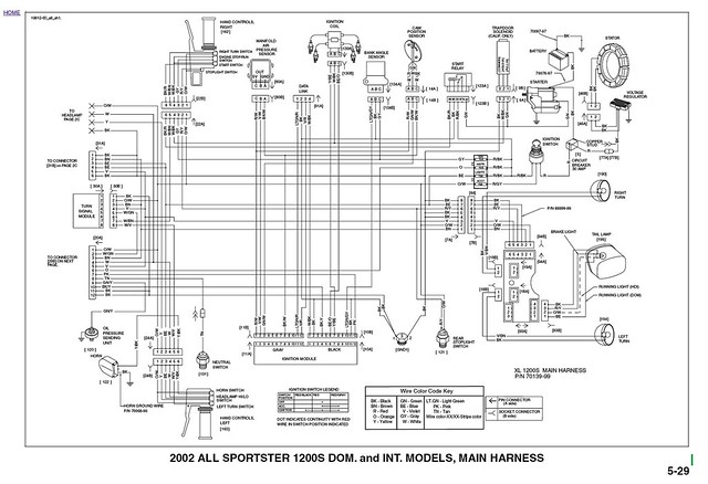
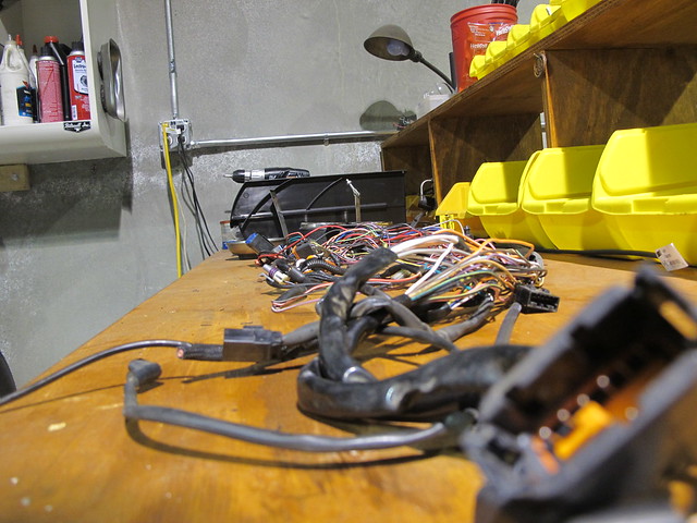
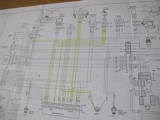
    An extremely helpful thing is a factory wiring diagram. I was lucky enough to get one from a guy in PDF form. I blew it up and printed it out onto eight pages, taped them together and hung it on the wall where I was working for reference. Once I thought I was sure about what was going where, I highlighted the wires I was keeping and you can see how many that left for the trash. I did my FXR the same way and a 90's era sporty without one and it was way easier to have a real diagram to reference.

    Tools needed:

    Test Light
    Crimpers / wire cutters
    Dialectric Grease
    Heat Shrink tubing 3/16" and 1/4" and a little 1/2"
    Electric heat gun
    Basic hand tools for removing mechanical parts
    Butt connectors
    Spade connectors
    Ring connectors
    1,000 Zip Ties
    Two-position Toggle Switch
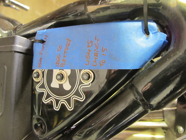
    2) 30 amp resettable circuit breakers
    1) 15 amp resettable circuit breakers
    Blue tape
    Sharpie

    Note: Remember how I said everyone does things differently? I use circuit breakers and solderless connections. Most people use solder and fuses and the factory uses auto-reset breakers. I don't care for those because I can't tell when one has popped and standing around waiting to see if one resets seems too passive. I wanna know, then I can chase the problem and try to figure out if there is a short somewhere. A lot of old desert racers swear that solder can make the wires brittle and prefer crimped type connectors (and resettable breakers, ever see the dash on an off-road race car?) Anyway, it's worked for me in the past, so why change? On the subject of solderless connections, I use the good ones, with no plastic insulation. I put a little dab of dialectric grease in each one, make sure it is crimped properly and use the smallest heat shrink possible for a tight fit. If you like solder, use it. Same with fuses, but put them somewhere you can get at on the road, not under a tank that takes twenty minutes to pull off. For switches and breakers, try to find the kind with screw-on connections, use your ring connectors in the proper size and put a dab of silicone or liquid electrical tape over the conection once you are sure everything is hooked up in the right place.

    Continued...
  • billdozer
    • Apr 2024

    #2
    old loom

    So the first we did was take off all of the wiring harness, without cutting anything. OK, maybe one or two wires, but that was after trying really hard to keep the whole thing intact. We left a few things in place so we could use factory cannon plugs to reconnect when we were ready. To do this, we removed all hand controls, gas tank, battery, battery box, seat and if it had a rear fender we would have taken that off too. The panel next to and behind the battery which housed fuses and circuit breakers was removed. If you have to cut a wire, make it in the middle if you can, so you have room to reconnect if need be, and strip back all the loom cover that you can before doing so, this way you can recreate the loom on the bench if you are trying to figure something out. Simply cutting wires you think you don't need, taping them up and stuffing them under the tank is not a great way to do this, though lots of people do it that way.

    Things we unplugged and left in place:

    Voltage regulator. No need to remove, just unplug the one wire that comes out and runs up towards the battery.

    The ignition module. It the two little boxes bolted under the seat, one grey, one black. Remove the factory cannon plugs and just leave it in place.

    Wires coming from the bottom of the engine with the triangular-shaped plug. This is coming from your stock ignition cam sensor plate.

    Positive wire that goes from battery to starter. No need to remove from starter. It's just going to go back on.

    Don't throw away anything from your stock loom, you are going to need lots of these little factory plugs. They work great, have the stock colored wire coming in and out of them, etc.

    Comment

    • billdozer
      • Apr 2024

      #3
      The next thing we did was figure out what physical things we needed and where they were going to go.

      A two-position toggle switch for the headlight was mounted in the existing hole on the outside of the top motor mount. We removed the stock acorn nut and plastic triangle thingy and drilled out the hole to accept the switch. Josh uses a high beam-only off road light, hence the two-position switch. You might use a three-position if you want a high beam, or you may choose to run it hard wired so the light comes on with the key and no switch is needed. (I like to be able to turn off the light if the battery is weak, just to conserve juice.)

      Obviously a headlight and tail light. Figure out where that tail light is gonna mount and how it will ground.

      ignition switch

      Backside of Battery Tray

      Ignition switch. We chose to relocate Josh's on the side of his battery box. I welded a small tab that it could rest on and so it couldn't rotate when turning the key. We drilled through the battery box and used the stock, single small bolt to hold it in place. I ground off the other castings in the plastic so it looks fairly round.

      Panel Clips

      circuit breakers

      Side Panel

      With all the stock breakers and whatnot out of the way rear of the battery, there is no way to hold on the metal cover. Clip-on nuts slide right over the tabs and give a good spot for SS 1/4x20 bolts to hold it all in place. We drilled this cover to accept the three resettable circuit breakers. This keeps them close to the battery and out of the way, but still accessible. We marked the breakers and held the panel in place with zip ties at first and then buttoned it all up at the end.

      Update: On the breakers, they are not wired like a fuse, where either connection can be used. Power should go into the connector marked "Line" and out to your accessory or whatever needs power from the "Load" connection. Thanks to Brandon for that super useful bit of information!

      Another thing we unlpugged but left in place was the stock, rear brake switch. No need to relocate it.
      Last edited by Guest; 03-26-2012, 9:39 PM.

      Comment

      • billdozer
        • Apr 2024

        #4
        That's the fun stuff, figuring out where to put stuff, how to mount it all cleanly, etc. Next, the work comes-making function.

        I looked at the factory wiring diagram and decided to highlight what we needed. The coil needs to get plugged in, so follow those wires to the ignition module. Note that one T's off and goes to the stock hand controls. This wire will need to be connected to the "IGN" side of the ignition switch. The wires we left hanging (with stock connector intact) coming from cam position sensor will need to end up connecting to the ignition module.

        I started with the black wire coming out of the voltage regulator. I found the stock plug in the loom, and the black wire that comes out of it. I trimmed back enough of the protective covering to get a good length of the stock wire and clipped it off. I added a few feet of the same gauge, same black color wire to the end, and plugged it into the connection still hanging on the bike. Then, fed the wire up under the engine, but on top of the frame rails (always!) and made sure it was out of the way of exhaust and any moving parts. I pulled it out near the battery and made sure I had an extra couple of feet just in case. This wire will send juice from your VR to your battery, it is your charging system, so route it nicely. Eventually, I terminated mine on one of the 30 amp breakers and ran a hot from the battery to the other post on that breaker. This way if the VR starts freaking out, the breaker will pop.

        Stock Coil Plug
        (Stock plug to coil)

        Next, I figured the coil needed some juice. I found the stock connector on the harness (on the bench), grabbed as much wire as possible with it and clipped it off. I patched in as much wire as needed (all black, but labeled on the end with tape) so those wires could reach their home at the ignition module. Then, I cut the cannon plugs off the bench loom, again leaving plenty of wire to be able to work with. Note that the Black/White wire T's off and goes to the "IGN" circuit brreaker to send power to the coil. I used a little extra from the loom so that this wire is the factory color. (Who knows who's working on this thing in ten years, might as well make it easy on us and them.) I took the labeled ends of these three wires and connected them to the appropriate wires on the stock ignition module cannon plug. Using the same procedure for the wires coming out of the Cam Sensor, I used the stock plug under the engine, added wire and tied it into the appropriate wires on the cannon plug at the module. Once both of the cannon plugs were pushed into the ignition module, there were a few wires left over. Rather than just leave them hanging or an unsightly tangle, I cut them to about six inches long (just in case we need them later) bent them over neatly and zip tied them in a little bundle. Once I confirmed that they were not needed (bike started and ran) I put a little piece of small heat shrink on each and then bundled them together and slipped a large piece of heat shrink over the bundle and sealed them up. This way if we ever want to go back, we can get at them, but in the meantime they won't be shorting out or causing problems.

        Ignition Module Bundle
        All wrapped up. The unused wires on the gray module were: V/W, LT GN/R and V/R. The unused ones on the black module were: BK/Y, LTGN/GY and PK.

        Two Black wires that come out of the Black module were grounded.

        This is a lot of reading, so looking at a revised diagram might help. Here's the highlighted one:

        Diagram

        and a hand drawn one I made:

        2002_Sporty_Diagram_Reduced

        That's all for tonight, I'll do the ignition switch and lights tomorrow after I proof this stuff to make sure I've got it right for ya.

        Comment

        • scottylook
          Senior Member
          • Sep 2009
          • 237

          #5
          Just did my 02 as well. So nice without all them dam wires. Great idea on those clip on nuts for the side iggy cover. I know the S model has some more needed wiring, great job. So did you ditch the voes all together? What ignition are you guys running?

          Comment

          • Wayland137
            Senior Member
            • Dec 2010
            • 136

            #6
            This is a great how to. Love the look!

            Comment

            • billdozer
              • Apr 2024

              #7
              Originally posted by scottylook
              Just did my 02 as well. So nice without all them dam wires. Great idea on those clip on nuts for the side iggy cover. I know the S model has some more needed wiring, great job. So did you ditch the voes all together? What ignition are you guys running?
              VOES is completely gone, stock ignition.

              Comment

              • scottylook
                Senior Member
                • Sep 2009
                • 237

                #8
                Originally posted by billdozer
                VOES is completely gone, stock ignition.
                Nice, are you notacing any ill effects. I have heard allot of different opinions on this

                Comment

                • billdozer
                  • Apr 2024

                  #9
                  Originally posted by scottylook
                  Nice, are you notacing any ill effects. I have heard allot of different opinions on this
                  Not yet. Bike only has a few miles on it so far, so I'll let you know if it does but so far it runs fine. I did the same thing on a '97 a couple years ago and ran that bike several thousand miles in lots of conditions, altitudes, etc and didn't have any probs.

                  Comment

                  • billdozer
                    • Apr 2024

                    #10
                    Once the coils, voltage regulator and ignition modules were all hooked up it was time for the simpler stuff; ignition switch and lights.

                    The stock ignition switch has three wires coming out the back. One is where power goes in, one is where power goes out in the "accessory" position, one is powered in the "ignition" position. Note, when the key is in the "ignition" position, power is also going to the "accessory" wire.

                    To figure out which wire is which, hook a jumper wire from the battery to one wire and then see which of the other two light up when the key is in various positions. Label these wires since they are all red.

                    We ran a power lead from the pos side of the battery to a 30 amp breaker and then over to the "Power in" wire on the back of the switch.

                    Then from the "accessory" wire, we ran a wire to a 15 amp breaker for the lights. Out of the other post on the breaker, a lead was connected to the headlight switch, the brake light switch and the tail light.

                    Check the hand drawn schematic to understand this better.

                    Don't forget that you generally have to ground your headlight and tail light. For the headlight, I run a wire back to the front tank mount on the frame, rather than let it ground through the head tube bearings. (Not sure if that's an old wive's tale or not, but it seems logical.)

                    I went ahead and started the bike and tested the lights before going back over everything and making sure that everything was zip tied together and to the frame or other hard parts to avoid chaffing or other damage. Always run wires above the bottom of the frame rails so they don't get scraped and watch out for things like swingarms, belts, chains and pullies.

                    Good luck and have fun!

                    Comment

                    • Incrediblah
                      Senior Member
                      • Aug 2010
                      • 473

                      #11
                      Thanks a bunch for this. I'm aaaaaaalmost ready to wire up my 99, and I was a little worried. This should help a lot.

                      Comment

                      • doppleganger87
                        Senior Member
                        • Dec 2010
                        • 355

                        #12
                        yea i agree..its nice to see how others have done theirs!i gutted my loom while home on leave and had to come back to the stan with my bike not in running order!ive been told by removing the switches on the bar i have to find a new hot wire for my pink wire on the coil..also need to wire the headlight back up..i still have the orange and white wires from i believe the turn signals if i remember correctly?that are hot wires that i think ill connect the headlight to and maybe wire my coil to a power out off the ignition..just an idea i had but im not entirely sure it would be the safest route

                        Comment

                        • TheSandman
                          Senior Member
                          • Apr 2011
                          • 722

                          #13
                          Thinking of doing this to my 02 if it doesn't sell.

                          Have you come up with anything for the horn or headlight switch location? That's the only problem I seem to be having before I dive into mine.

                          Curious to see other's ideas too.

                          Comment

                          • Hedstrong
                            Member
                            • Apr 2011
                            • 94

                            #14
                            Damn you Bill! I was just going to move my Coil and now "I am back into the wiring harness again.

                            Comment

                            • Hedstrong
                              Member
                              • Apr 2011
                              • 94

                              #15
                              Hey Bill or anyone really. I am redoing a 96 sportster with this guide and my main circuit breaker is a 50amp. I got 2 resettable 30's, can I get buy with the 30 amp breakers or is this thing really in need of the 50?

                              Comment

                              300 mobile ad bottom forum

                              Collapse
                              Working...
                              ;